
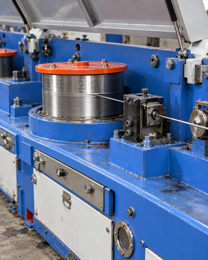
Steel Wire Feedstock for Welded Mesh Production Lines
Choose welded-mesh wire around the crossing sizes, coating sequence and actual line behavior. This guide helps you connect the supplied wire condition with straightening, feeding and intersection welding. You can then plan a fair trial that checks wire dimensions, joint results and finished-panel geometry as separate parts of the same production decision.
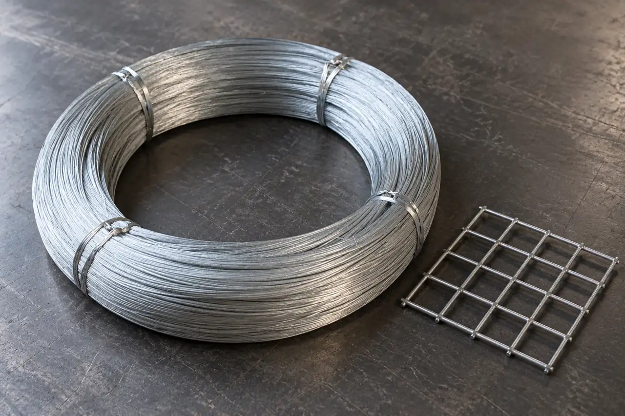
Build the wire brief from the mesh route
For a welded-mesh producer, choose one low-carbon wire grade, actual round section and delivery condition that feeds consistently and supports the qualified intersection-welding process. Decide whether zinc is applied before or after welding; pregalvanized and bare wire are different process inputs. Relia manufactures steel wire with in-house drawing, annealing and galvanizing and can discuss the listed candidates against your mesh specification. Start with longitudinal/transverse wire sizes, mesh pitch, surface route and required joint tests. Approve straightening, feeding, weld consistency and final geometry on the actual line rather than accepting a general netting or construction label.
- Crossing sizesIdentify longitudinal and transverse wire dimensions alongside mesh pitch and panel geometry.
- Surface sequenceState whether galvanizing occurs before or after the intersection-welding operation.
- Line acceptancePlan input, weld and panel checks around the actual production procedure.
Selection context and decision detail
| Buyer requirement | Relia response | Evidence or condition |
|---|---|---|
| Mesh feedstock | Own drawing, annealing and galvanizing | One round-wire grade, condition and surface required |
| Weld-compatible input | Discuss bare or coated wire separately | Actual intersection procedure and tests control approval |
| Batch evidence | Incoming, process and final records can be provided | Wire conformity does not qualify the completed panel |
Wire production evidence belongs beside the mesh route
Use batch-linked wire production evidence for feedstock acceptance while keeping finished-mesh welding and geometry approval separate.
Relia carries out steel-wire drawing, annealing and galvanizing in-house, with incoming, process and final inspection and corresponding batch records available. Define which operations establish the offered wire's final condition and surface for your line.
Our wire conformity evidence supports the supplied feedstock. Finished-mesh welding, geometry and any load rating remain separate acceptance decisions. Identify your welding/coating sequence and required wire characteristics so the selected batch records address the input without implying that a general wire listing qualifies the completed mesh.
- Wire identityGrade, section and supplied condition
- Production evidenceConfirmed wire stages and batch records
- Mesh approvalSeparate input, joint and panel acceptance
Resolve round-wire and coating identity before the trial
Define round section and one actual coating condition before comparing the selected mesh-wire candidates.
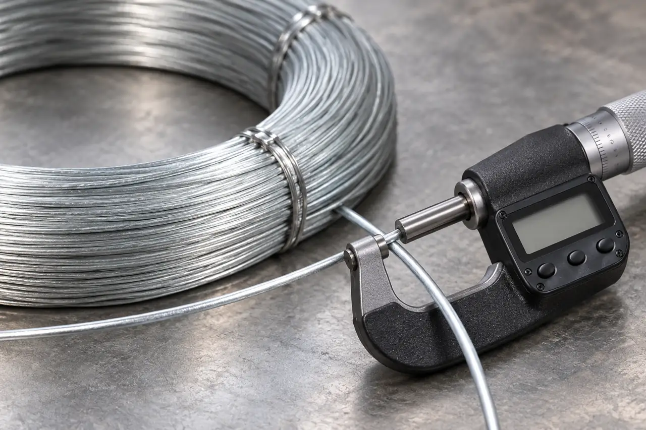
Select the surface entering the electrodes
The HH-GW01 galvanized listing has actual 1.8, 2, 2.5, 3, 5, 8 and 10 mm options, but retains Flat Wire wording. Confirm round section for a round-wire mesh line; 0.8 mm appears only as a title request.
The annealed mesh-wire listing has ten actual diameter labels from 1 to 10 mm and several material/surface alternatives. Select one grade, annealed condition and uncoated, galvanized or other agreed surface. Neither broad family description supplies a numerical weld-capacity or finished-fence rating.
- Pregalvanized inputDefine the zinc-coated wire condition and review its interaction with the welding process.
- Uncoated inputSpecify bare wire where coating is applied later in the finished-mesh route.
- Round sectionConfirm actual section and diameter for the feed and straightening arrangement being used.
Product references for your shortlist
Open the product details, then discuss the exact specification for your application.
Galvanized wire for mesh trials
A coated-wire enquiry route when the approved mesh process welds wire supplied with an identified zinc coating.
Annealed carbon wire for mesh
A carbon-wire reference for selecting a defined annealed condition and surface for straightening and intersection-welding evaluation.
Contact resistance and electrode condition influence the joint
Review current, time, force and electrode contact together when wire size or coating changes the welding window.
Resistance welding generates heat through current flowing at the contacting wires under force. Current, duration, contact geometry, material and surface condition interact. A wire-size or coating change can therefore alter the welding window even when the machine programme is unchanged.
Zinc-coated inputs also affect electrode contact and wear. Treat general coated-sheet guidance as mechanism, not numerical mesh settings. Establish the actual intersection-welding parameters and electrode maintenance through the applicable line procedure and representative joint tests.
- ContactActual crossing-wire geometry
- Heat/forceQualified current, duration and pressure route
- ElectrodeCondition and coating interaction
- TestSpecified joint result
Drawing condition and payoff affect mesh geometry
Connect supplied condition and coil geometry to straightening response, feed position, mesh pitch and panel flatness.
Drawing and annealing influence wire strength, ductility and straightening response. Coil cast, helix or package crossovers can disturb feed or leave residual curvature. Mesh pitch and flatness can drift even when the nominal diameter matches.
Record the wire's actual section, condition and coil arrangement with straightener settings and line tension. Separate a feed-position error from a weak weld when inspecting the finished panel. Changing welding current cannot correct every dimensional fault caused upstream.
- Material conditionStrength and straightening response
- CoilCast, helix and crossovers
- FeedPosition and tension
- PanelPitch and flatness readings
Acceptance should include wire, joints and the finished panel
Inspect input dimensions, intersection welds and panel geometry separately because one result cannot establish the others.
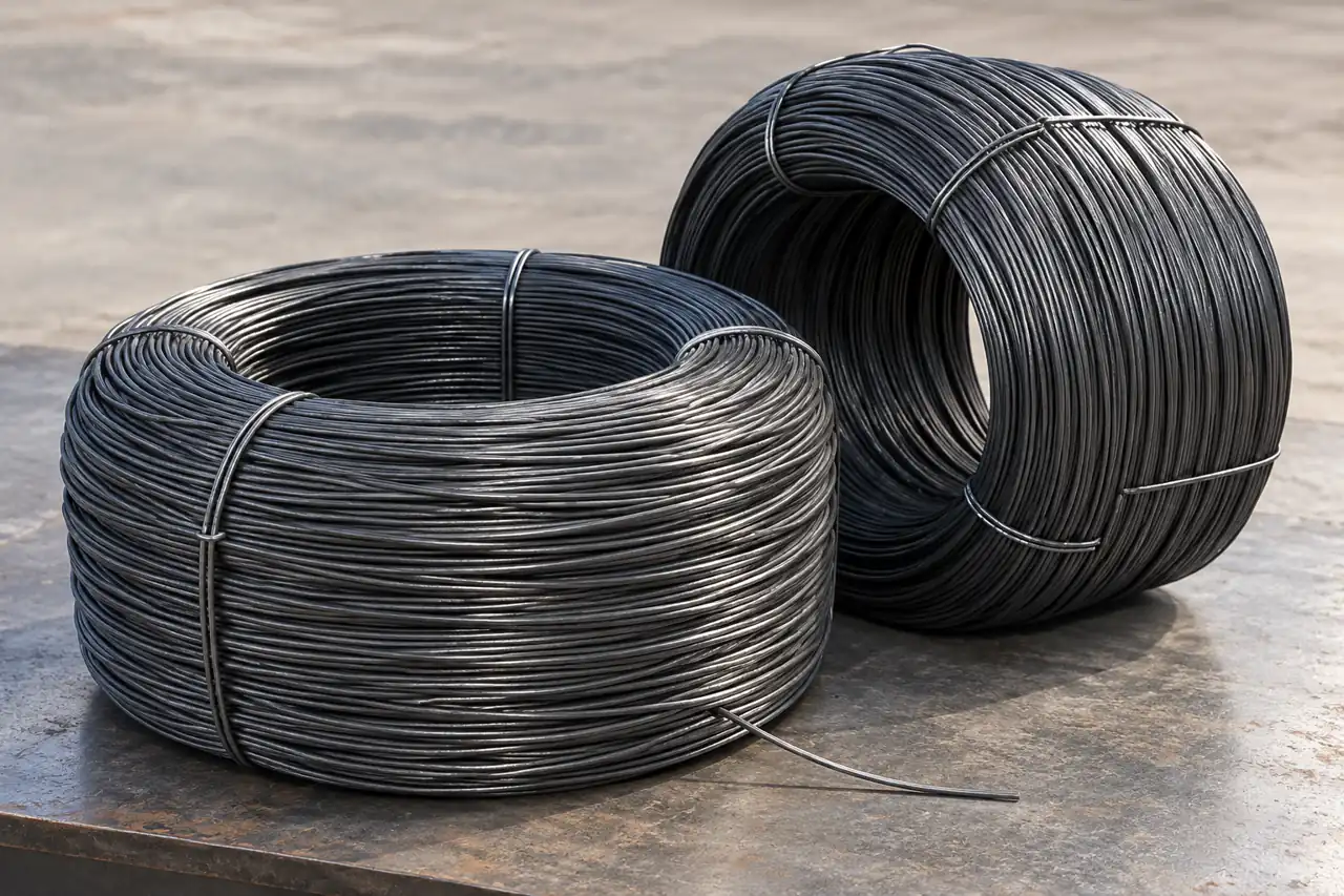
Three results complete the mesh-wire decision
Measure input diameter and relevant ovality at stated locations, then assess the actual intersection weld by the specified method. Inspect panel dimensions, pitch, flatness and surface condition separately. A wire tensile result cannot establish the shear or pull behavior of a weld.
The coil image is an AI-assisted receiving reference, not a batch measurement. Keep corresponding wire records linked to actual panel samples and test results. The initial illustrated micrometer does not supply a reading or a defined sampling plan.
- Input wireMeasure the required diameter and shape characteristics with the supplied batch identified.
- Intersection jointAssess the actual crossing weld by the method required for the mesh.
- Finished panelCheck pitch, dimensions, flatness and surface condition independently of wire tensile evidence.
A baseline trial distinguishes material and machine effects
Run comparable geometry and settings, recording stops, electrode condition and accepted panels to distinguish material from machine effects.
Run baseline and candidate on comparable mesh geometry, wire crossing sizes and production settings. Record feed stops, weld rejects, electrode condition and accepted panels. Keep deliberate coating, grade or diameter changes visible.
If one variable is altered at a time where practical, the result explains which change mattered. When a coating route changes, review the qualified weld and final protection requirements together rather than assuming a bright feed wire delivers the same finished coating after welding.
- BaselineSame mesh geometry and identified wire
- Recorded conditionsFeed, weld and electrode state
- ResultsStops, rejects and accepted panels
- DispositionChange and approval scope
Coil protection and identification preserve the line reference
Match coil handling and identification to the line, keeping longitudinal and transverse wire sizes clearly distinguishable.
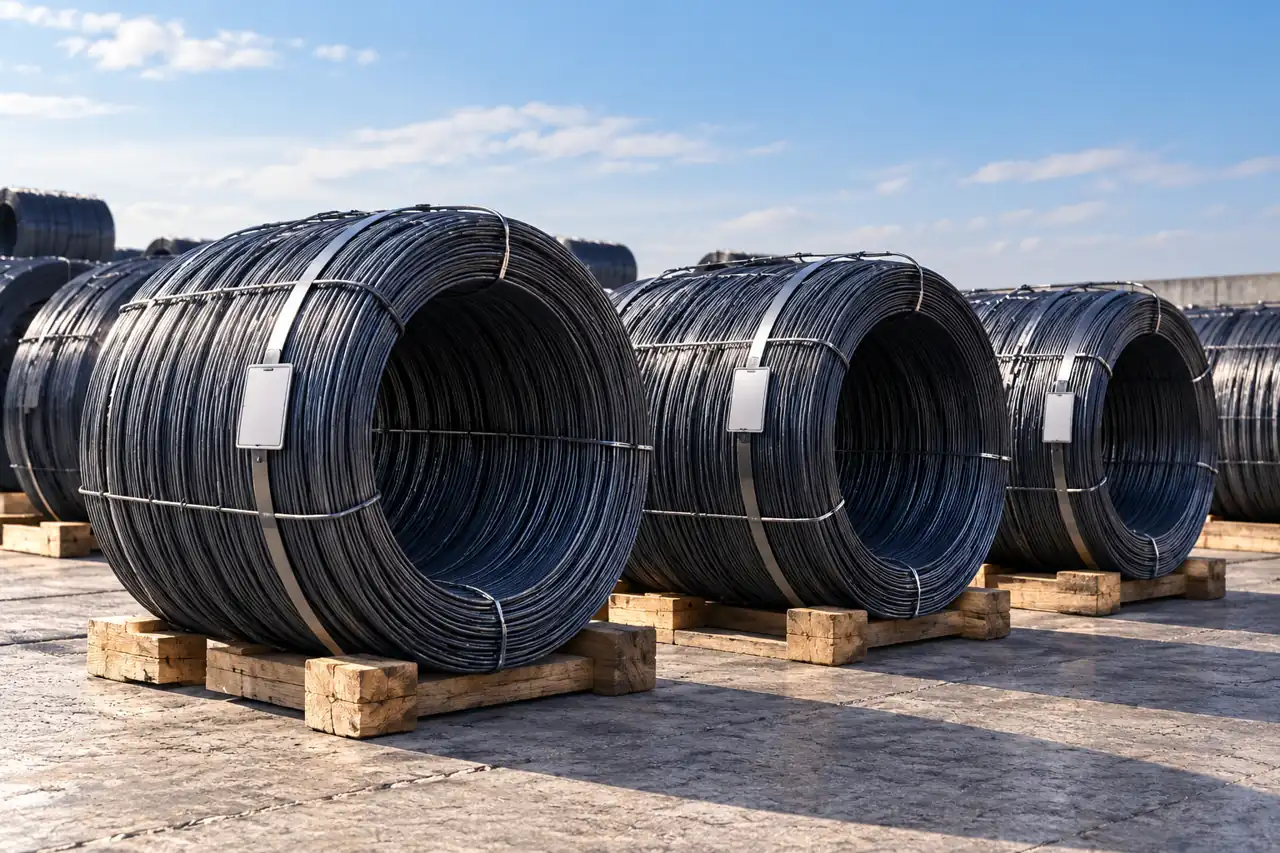
Keep the feedstock identity at each line position
Agree coil envelope, unit mass, payout and protection against the handling system. Keep grade, diameter, surface and batch identity distinguishable after receipt. Damage or moisture can affect feeding and the condition entering the electrodes.
The staged coils and blank tags are AI-assisted storage illustrations, not an actual shipment or proof of a label service. For mixed wire sizes, reconcile each pack with its order line before issuing material to longitudinal or transverse feed positions.
- Handling interfaceMatch coil envelope, mass and payout with the receiving and payoff arrangement.
- Surface protectionRecord moisture or damage that can change feeding and electrode contact condition.
- Wire positionReconcile each pack before issuing different sizes to longitudinal or transverse feeders.
A deviation needs the affected panel and wire sample
Retain the affected panel and wire evidence so joint faults and geometry drift follow the right investigation.
For a weak joint, retain the wire sample and corresponding panel with the location, electrode condition and settings. For geometry drift, retain pitch/flatness readings and feed observations. A later failure cannot be assigned to steel chemistry from the appearance alone.
Use the approved grade, condition, surface and coil arrangement as the replenishment baseline. Review any change in source or processing with the wire evidence and line trial required by the mesh specification.
- ObserveJoint or geometry failure
- RetainPanel, wire and batch record
- ReviewMaterial, feed and welding evidence
- ApproveDefined corrective action or supply revision
Define both wire positions and the weld requirement
Send crossing-wire sizes, coating sequence and joint requirements together to define the feedstock offer and line trial.
Share the crossing-wire schedule and coating route so we can discuss a wire package and trial evidence that separate feeding, joint and panel acceptance.
Qingdao Relia Industries Co., Ltd.
Contact address: Shuyuan Road, Qingdao, Shandong, China
- Longitudinal and transverse wire sizes
- Mesh pitch and panel dimensions
- Selected grade and coating sequence
- Payoff straightening and coil limits
- Joint tests and current line defects
Enquiry scope and supporting detail
Send both wire sizes, mesh pitch and panel dimensions, selected grade and surface, and whether galvanizing occurs before or after welding. Include straightening/payoff constraints, welding process reference and the joint/geometry tests that govern acceptance.
Add current defects, representative trial quantity, coil dimensions and destination. Request the offered round-wire identity and corresponding batch records with the quotation so the candidate can be assessed against a defined feedstock and welded-mesh route.
- RouteWelding and coating order with final requirements
- WireDiameter, condition and coil-handling limits
- ValidationTrial quantity, joint checks and acceptance records