
Aluminium Tube Supply for Equipment Frame Drawings
Choose aluminium frame tube by alloy-temper, section geometry and the joint you need to make. This guide helps you define clamp fit, wall and ovality, then assess critical bends or welded joints in the actual supplied condition. You can also place anodized appearance acceptance at the right stage of the fabrication sequence.
Specify the tube around the frame interfaces
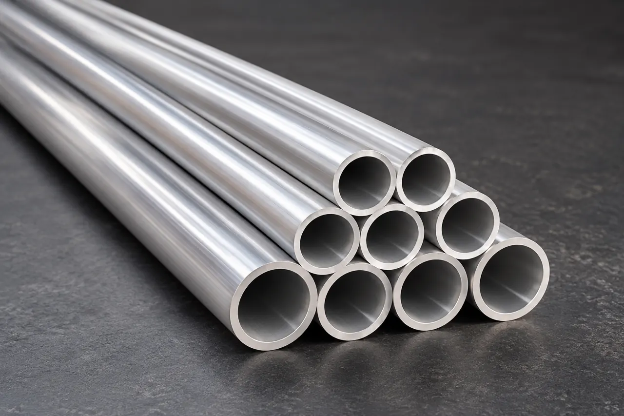
For an equipment frame or rail, select aluminium tube by alloy-temper, actual section and joint method before choosing a diameter class. A tube that looks smooth may still have the wrong wall, bending response or clamp fit. Relia's 6061/6063 listing supports a defined supply enquiry, but its broad options and conflicting temper fields need resolution. Send the round-tube drawing, bending or welding sequence and visible-finish requirement so the offer can identify compatible stock and a trial that checks the final assembly rather than appearance alone.
- Material conditionSelect the exact alloy-temper required for the intended forming and joint sequence.
- Section and fitDefine actual diameter, wall and shape limits where clamps and sleeves engage.
- Finished stageState when geometry and visible finish determine acceptance of the fabricated assembly.
Selection context and decision detail
| Buyer requirement | Relia response | Evidence / condition |
|---|---|---|
| Assembly-compatible tube | Aluminium supply and selection support | Actual OD/wall, alloy-temper and joint drawing |
| Usable fabricated condition | Trial and responsibility review | Bend geometry, weld effects and finish sequence |
| Traceable supply | QC and batch-record scope agreed | Producer, material identity and measured geometry |
Aluminium tube supply needs a defined producer and condition
Define the aluminium producer and supplied condition without assuming extrusion, heat treatment or anodizing is performed in-house.
Relia can support selection and supply from the aluminium tube catalogue; in-house aluminium extrusion, drawing, heat treatment or anodizing has not been confirmed. Company incoming, in-process and final QC with corresponding batch records is confirmed, while the inspection scope and producer responsibility for this supply must be agreed.
The listing offers diameter classes plus 3–250 mm/custom OD and 0.3–50 mm/custom wall, but the body describes 0.3–5 mm wall. It names 6061/6063, anodized surface and O–H112 alongside Full Hard. These fields do not establish a particular T6 tube.
- Selected producerIdentify the actual aluminium tube producer and scope of any included further processing.
- Alloy and stateConfirm exact alloy-temper and compatible section dimensions before adopting any mechanical requirement.
- Relevant recordsAgree producer and receiving evidence applicable to the actual tube supply being offered.
Alloy and temper determine more than a strength label
Use a verified alloy-temper designation rather than treating the alloy name or a hardness label as the delivered condition.
6061 and 6063 are distinct alloy identities; a heat-treatment temper describes a delivered condition, not merely hardness. For heat-treatable aluminium, thermal history influences the strengthening condition and fabrication response.
Specify the required alloy-temper and represented material evidence. Resolve the catalogue's mixed condition wording before adopting any mechanical value or substituting one alloy for another.
- AlloyRequired and proposed designation
- TemperActual supplied condition
- ReviewWritten approval of any alternative
Product references for your shortlist
Open the product details, then discuss the exact specification for your application.
Aluminium round tube for frame trials
A supply reference for a defined aluminium alloy-temper and round section evaluated through equipment-frame fitting, bending or joining.
Wall and ovality matter at different assembly interfaces
Specify diameter, wall, ovality and end geometry where they control clamps, sleeves and seated joints.
Different tube dimensions control different fits
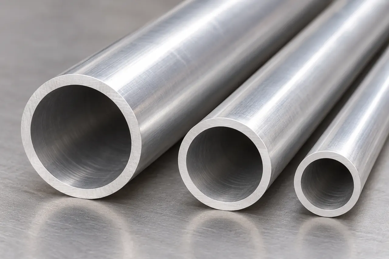
Outside diameter controls a clamp or sleeve; wall and local section govern the available material at holes and joints. Ovality can prevent assembly even when one diameter reading appears correct. Straightness matters along a rail, while end squareness matters at a seated joint.
State measurement locations and the acceptance stage. Diameter classes are navigation aids, not finished dimensions.
- Diameter and ovalityCheck the full shape relevant to clamp or sleeve engagement, not one diameter reading.
- Wall and jointsDefine the section needed at holes and connections against the actual drawing.
- Straightness and endsSet rail straightness and end squareness where they affect seating and assembly.
Bending should be assessed in the supplied condition
Trial the critical bend in the supplied condition, checking cracking, flattening and final fit before extending approval.
Trial the critical bend radius, tooling and support on the proposed alloy-temper. Examine outer-surface cracking, flattening and the dimensions needed by the frame. A softer forming condition and a strengthened condition do not automatically offer the same combination of bendability and final properties.
Record the condition and setup, rather than extending a successful bend to every wall or diameter.
- SelectVerified alloy-temper and section
- BendCritical radius with recorded support
- InspectCracking, flattening and fit
- RetainActual trial condition and geometry
Welded joints require a final assembly basis
Assess welded joints under the frame design because the heat-affected region cannot simply inherit parent-tube properties.
Define the welded frame acceptance basis
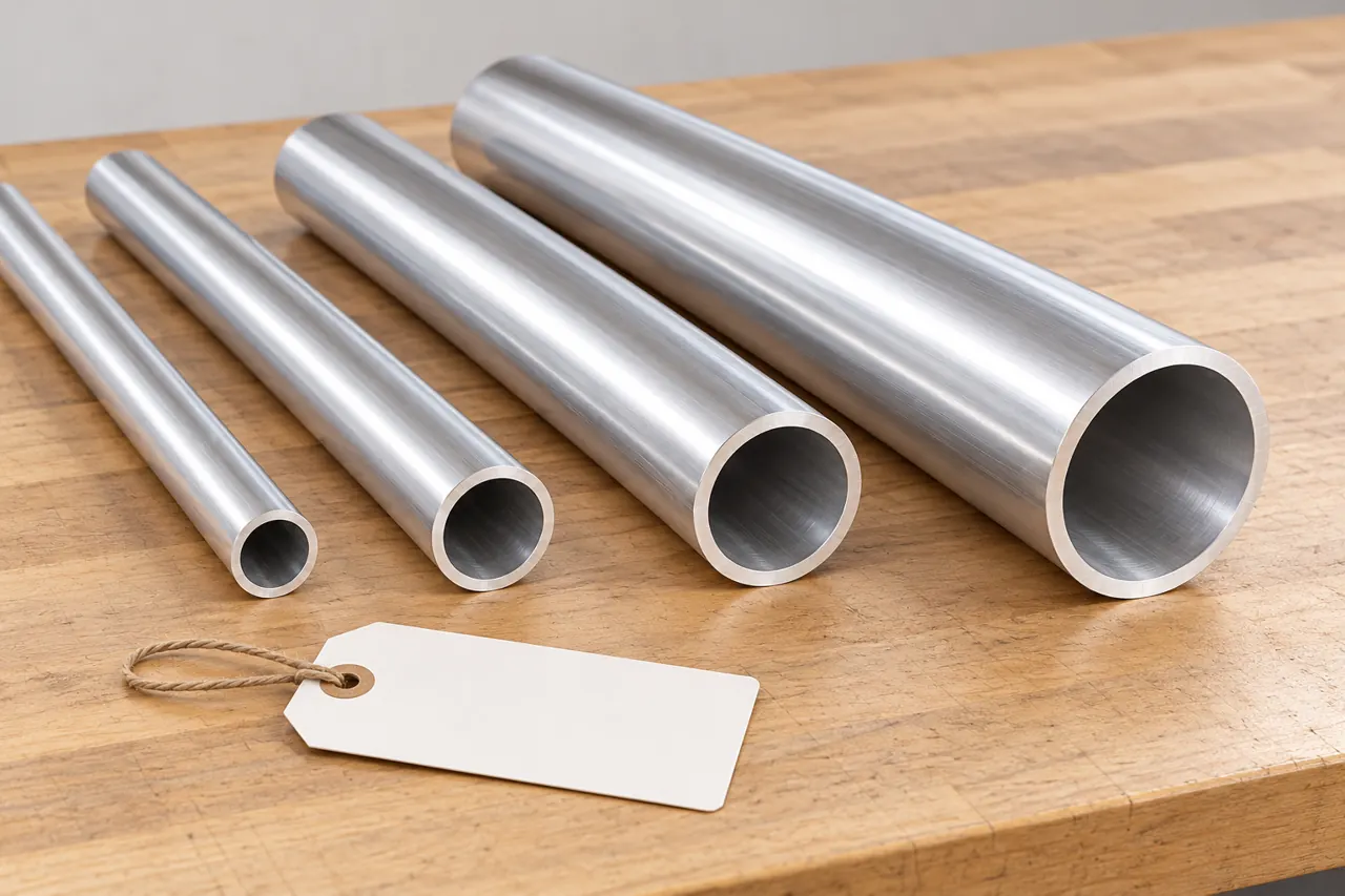
Fusion welding can reduce strength in the region of a heat-treated 6061 tube. Parent-tube properties therefore should not be copied onto a welded frame without the appropriate joint and design basis.
Define the joining responsibility, filler/procedure selection and final acceptance through the responsible fabricator and engineer. No frame capacity or post-weld heat-treatment service is implied.
- Supplied stateIdentify the actual alloy-temper used for the selected tube and joint trial.
- Joint responsibilityAssign the procedure and filler selection to the responsible fabricator and engineer.
- Final assemblyAssess required joint behavior and dimensions without copying parent-tube properties onto the welded frame.
Anodized appearance must be located in the sequence
Locate appearance acceptance after the relevant cutting, bending and joining operations rather than relying on anodized wording alone.
Specify whether the visible finish is assessed before fabrication or after all bending, cutting and joining. Those operations can mark, expose or locally change the delivered surface. Identify visible faces, colour reference and protection where appearance matters.
Anodized wording alone does not define coating thickness, wear performance, electrical isolation or a finished-part approval.
- Accepted stageState whether the finish is assessed before fabrication or after cutting, bending and joining.
- Visible referenceIdentify exposed faces and the required colour or appearance reference at that stage.
- Surface protectionAgree protection and handling where fabrication can mark or expose the delivered finish.
Pack protection should match thin-wall and visible surfaces
Protect thin-wall ends and visible faces while preserving tube identity as lengths become frame components.
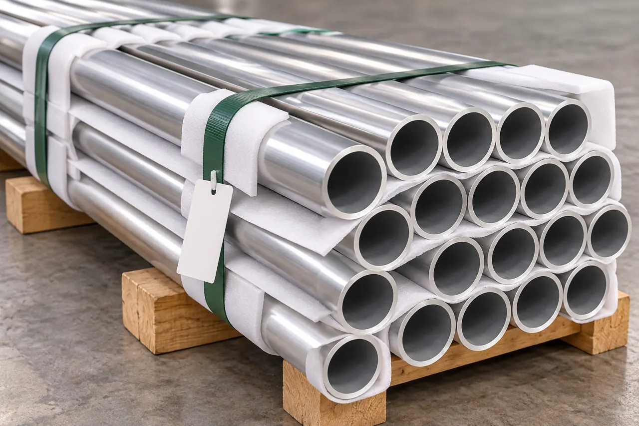
Protect the surfaces and section that matter
Use the receiving brief to identify end protection, contact marks and the actual supplied dimensions. Keep material identity with the tube lengths as they are cut into frame components.
The separated bundle illustration is relevant to protection, but it cannot prove the alloy-temper or guarantee that every packaging arrangement is included.
- Thin-wall endsIdentify end protection and handling contact appropriate to the actual supplied section.
- Visible surfacesAgree protection against contact marks where the delivered finish remains exposed.
- Cut-length identityKeep alloy, condition and source references with lengths as frame components are prepared.
The release package should preserve geometry and condition together
Keep material condition, section limits and accepted bend or joint evidence together when reviewing a release or substitution.
Link the selected alloy-temper, diameter/wall limits, surface and producer to dimensional and material records, then retain the accepted bend or joint trial. Review substitutions before a changed temper or wall enters the frame line.
Company QC capability does not establish a particular test method, inspection frequency or numerical strength result for this tube.
- IdentityProducer, alloy and temper
- DimensionsOD, wall, ovality and straightness
- FabricationAccepted bend or joint result
- SurfaceFinish at defined final stage
Define the tube and assembly interfaces
Send the actual section and fabrication interfaces to define a selected tube configuration and representative assembly trial.
Share the frame drawing and critical clamp, bend or joint so we can discuss an identified tube condition and a trial matched to your assembly.
Qingdao Relia Industries Co., Ltd.
Contact address: Shuyuan Road, Qingdao, Shandong, China
- Exact alloy temper and section
- OD wall and ovality limits
- Clamps bends and joint details
- Finish and dimensional acceptance stage
- Lengths quantities and required records
Enquiry scope and supporting detail
Send actual OD, wall, lengths, required alloy-temper and critical straightness or ovality limits. Include clamps, bends, holes or welded joints and the stage at which finish and geometry are accepted. We can then define supply responsibility and a representative trial, with documentation, quantity and schedule confirmed for that exact configuration.
- DrawingSection, wall, length and revision
- ConditionAlloy, temper and surface
- SupplyQuantity, documents and destination