
Drawing-Based Steel Warehouse Component Procurement
Buy warehouse components around an approved drawing package, not a building size label. Define the member groups, loose connections and interfaces that must arrive ready for the agreed assembly sequence. This guide helps you connect material and fabrication evidence, resolve responsibilities and keep the supplied package identifiable from the quotation through site receiving.
Define the warehouse component deliverable
For procurement teams with an approved warehouse design, buy a defined component package rather than a building-size label. Relia can review the listed steel-structure enquiry against your member schedule, drawings and required records; engineering, fabrication, coating and installation responsibilities need an explicit offer. The purchasing decision is whether the delivered members and loose connections fit the approved interfaces and can be identified in the erection sequence. Send the drawing revision, site design basis, material schedule and quantities so unresolved geometry, exclusions and inspection hold points are settled before material or fabrication is released.
- Approved geometryUse the governing design and detail revisions for member and connection interfaces.
- Member scheduleSeparate material, section, condition and quantity for each supplied component group.
- Supply responsibilitiesState fabrication, protection, documents and site work included in the actual package.
Selection context and decision detail
| Buyer requirement | Relia response | Evidence or condition |
|---|---|---|
| Components that fit the approved design | Review the drawing-based supply package | Member marks, interfaces and one revision |
| Traceable inspection | Batch records can be provided | Confirm actual producer and project record scope |
| Complete project boundary | Identify fabrication and site responsibilities | No assumed design or installation package |
Separate component supply from building design
Identify actual component production and supply responsibilities separately from Relia plate and pipe manufacture.
Relia manufactures steel plate/coil and steel pipe; this does not establish every warehouse member, fabrication operation or installation service as in-house. Incoming, in-process and final inspections are performed and corresponding batch records can be provided. Identify the actual component producer and the records relevant to this package.
The HH20240404w listing has six type/colour/size combinations. Its 120*70 and 140*70 labels lack units and axis definitions, while Q235B/Q345B and sandwich-panel fields describe possible materials. None establishes approved span, loads, complete design or installation responsibility.
- Design authorityApproved loads, geometry and acceptance requirements
- Supply authorityActual member producer and defined component schedule
- Site authorityFoundation, erection and installation responsibilities
Attach material evidence to each member group
Connect the selected material for each member group to its own represented steel and fabrication checks.
Keep material and finished member checks distinct
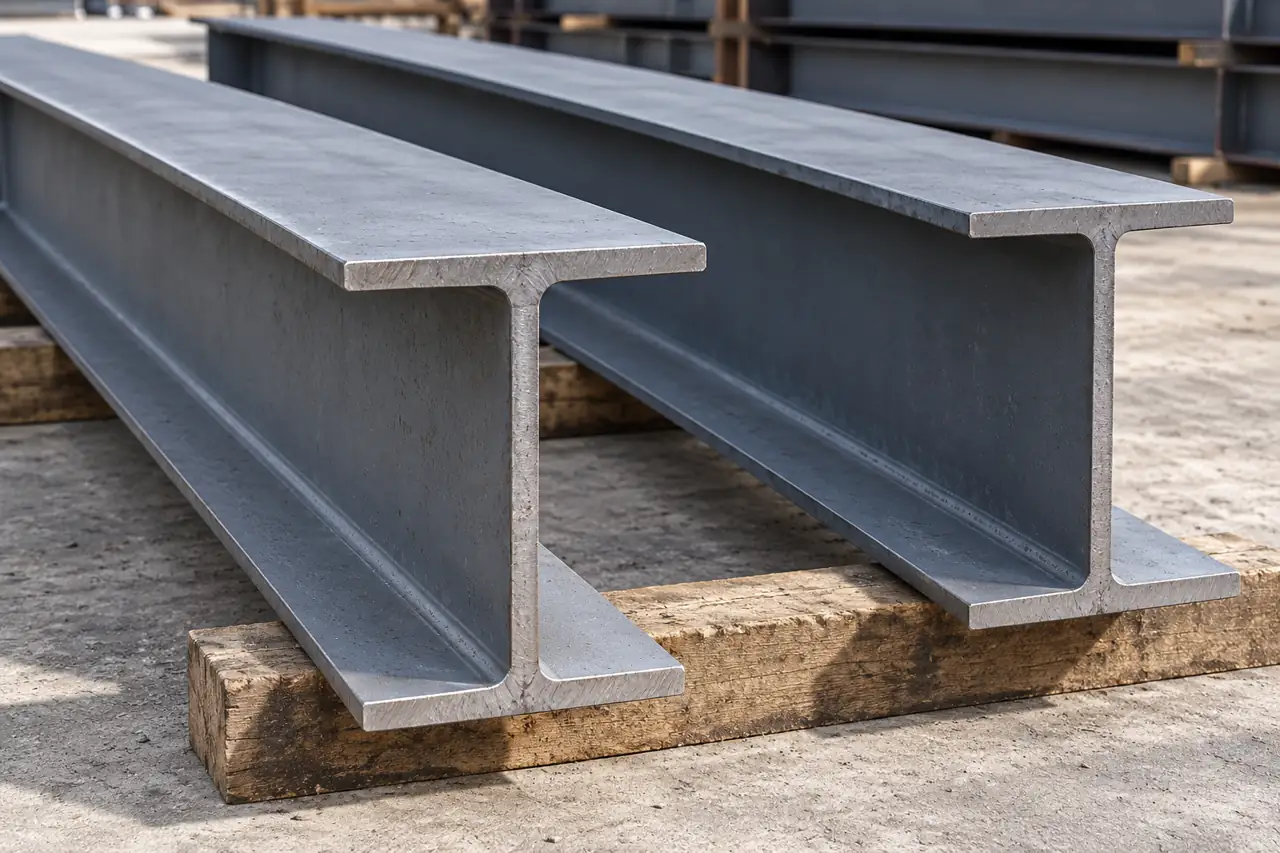
List columns, beams, plates, bracing and any cladding separately, with the requested grade, section, condition and quantity. Do not apply one broad steel-grade list to every component. Keep plate or section material identity through cutting and fabrication, including loose connection plates. A material report supports the represented steel; it does not prove that the finished member has the correct length, hole pattern, weld or coating.
- Material identityConnect each grade and represented heat or lot with the intended member group.
- Fabricated geometryReview the member dimensions, orientation and hole pattern against the accepted drawing.
- Project releaseLink the required weld and coating evidence to the represented member marks.
Product references for your shortlist
Open the product details, then discuss the exact specification for your application.
Drawing based steel warehouse package
A starting enquiry for an approved component schedule with defined member, cladding and connection supply responsibilities.
Fabrication changes the fit that the drawing controls
Cutting, hole making, welding and protection can change the geometry and interfaces controlled by the drawing.
Cutting and hole-making establish connection geometry; assembly and welding can introduce local movement as heated regions cool. Surface preparation and coating add further interfaces and may affect contact or protected areas. Define the manufacturing sequence and inspection stages relevant to the actual member instead of accepting only a final appearance photograph.
Check critical geometry at the stage where it can still be corrected under an approved disposition. This is a general fabrication mechanism, not a claim of a particular Relia welding line or coating facility.
- PrepareControlled detail and selected material
- FabricateActual cutting, holes, assembly and welding scope
- CheckMember geometry and required fabrication evidence
- ProtectAgreed surface preparation/coating and identification
Resolve connection interfaces before the affected work
Resolve member orientation, mating holes and foundation interfaces before the affected components are fabricated.
Put end plates, bolt holes, member orientation and mating parts on one consistent revision. A hole group may have correct individual diameters yet fail because its position or orientation is wrong. Foundation and anchor interfaces require coordination with the project authority, not an assumed adjustment on site. Return conflicts and proposed changes for a written decision before the affected members are fabricated.
- Member interfaceEnd position, orientation and mating geometry
- Connection setHole pattern, plate thickness and included fasteners
- Site interfaceFoundation/anchor references and erection clearance
- Change controlAccepted revision and authorized disposition
Define records at material and fabrication release
Define project records at the stage where relevant features can still be examined.
Agree which material, dimensional, weld, surface-preparation or coating records the project requires, and who issues them. Some evidence must be obtained before an area is concealed or coated. Identify the represented member marks, inspection stage, acceptance reference and any witness or review point. Relia's confirmed batch-inspection practice does not establish a particular test instrument, structural certification or numerical inspection frequency for every supplied component.
- MaterialGrade and represented heat/lot
- FabricationMember mark, stage and applicable acceptance
- ProtectionSelected system and required measurements
- ReleaseAccepted deviations and document package
Include loose connections in the component count
Count and identify loose connections with the same control used for the major members.
Control the small connection items
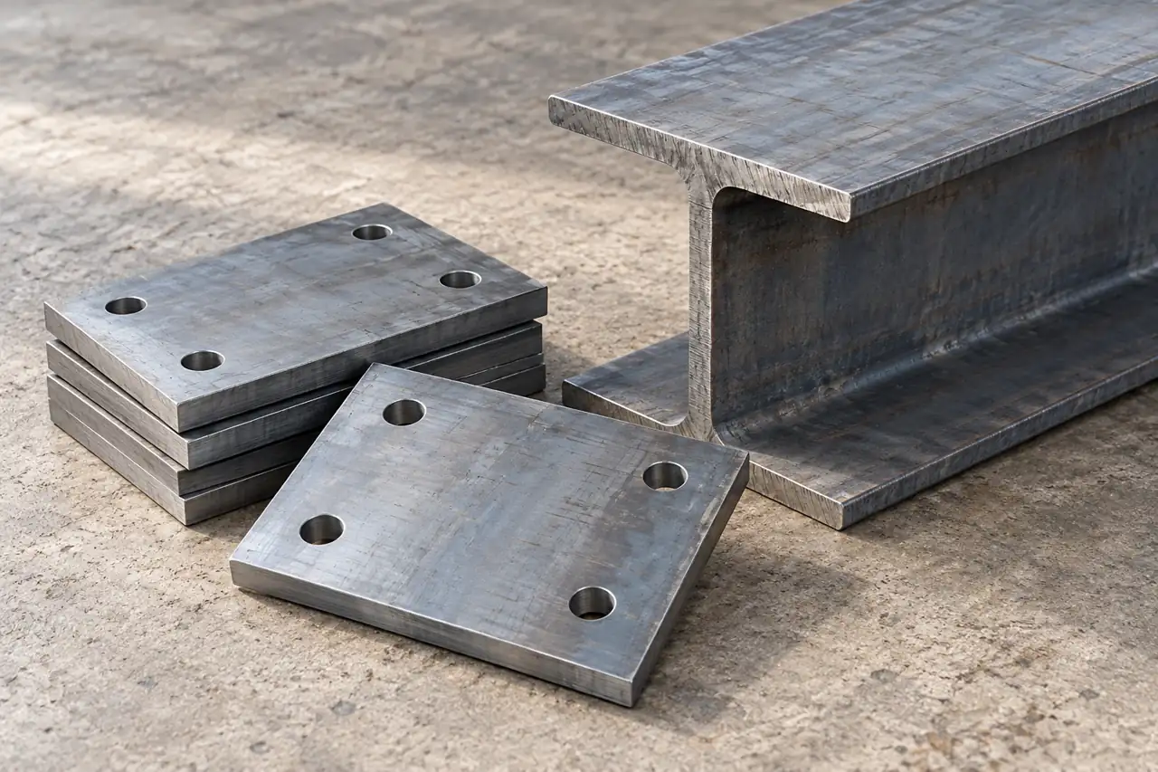
Connection plates, bracing fittings and other small items need controlled references and quantities just like major members. Separate supplied bolts, anchors and accessories from items provided by the site or another contractor. Use the drawing and packing list to identify them after a main bundle is opened. A visually similar plate with the wrong orientation or hole spacing can interrupt assembly despite representing little shipment mass.
- Loose item scheduleGive connection plates, bracing fittings and accessories controlled references and quantities.
- Supplied scopeSeparate included bolts and anchors from items supplied by the site or others.
- Assembly connectionKeep loose packs linked to the relevant member marks after bundles are opened.
Pack around the receiving and erection sequence
Plan delivery groups, support and identification around receiving and the intended erection sequence.
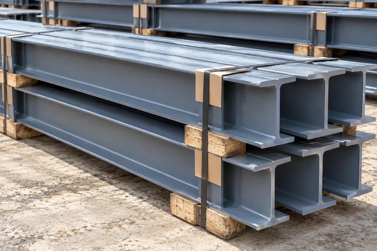
Prepare delivery around receiving and erection
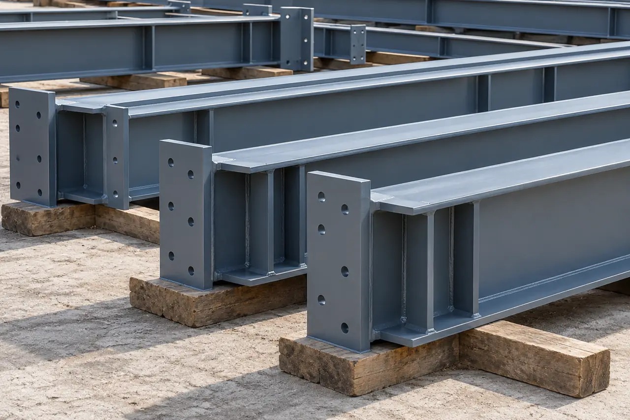
Agree support, lift access, bundle identity and surface protection for the actual member lengths and masses. Coordinate delivery groups with the receiving plan rather than assuming that container loading order equals erection order. Keep loose-item packs linked with the relevant member marks, and record damage before unloading or further handling changes it. The illustration shows supported steel members, not a verified lifting design or a dispatched warehouse project.
- Group the materialCoordinate identified member and loose item groups with the actual receiving plan.
- Protect the packageAgree support, lift access and surface protection for the selected member geometry.
- Record the arrivalDocument marks, quantities and damage before handling or field work changes the condition.
Keep package exclusions visible in the comparison
Compare the same component and service boundary while keeping design and site exclusions visible.
Compare the same approved drawing set, member list, materials, fabrication, protection, records and delivery boundary. State design/detailing, foundations, installation, site equipment and optional work separately. A catalogue promise of installation or a generic warranty does not define the project contract. If a discrepancy occurs, preserve member orientation, marks, drawing revision and readings before a proposed field correction is reviewed by the responsible project team.
- Component packageCompare the same drawing set, member list, materials, fabrication, protection and required records.
- Design responsibilityState design and detailing responsibilities separately from the offered component supply.
- Site work scopeIdentify foundations, installation, site equipment and optional work explicitly in the project comparison.
- Correction evidencePreserve member orientation, marks, drawing revision and readings before project review of field corrections.
Prepare the approved component and interface package
Send the approved drawings and material schedule to define the actual component offer and responsibilities.
Share the approved member schedule and the site interfaces your team must coordinate. We can clarify the supply candidate, responsible producers and evidence required for the package.
Qingdao Relia Industries Co., Ltd.
Contact address: Shuyuan Road, Qingdao, Shandong, China
- Governing design and detail revisions
- Component grades sections and quantities
- Connection and foundation interfaces
- Inspection coating and record requirements
- Delivery groups and site exclusions
Enquiry scope and supporting detail
Send the governing design and detail revisions, component/material schedules, quantities and destination. Add connection and foundation interfaces, inspection/document requirements, protection system and delivery grouping. Relia can clarify the listed supply enquiry and actual producer responsibilities. Design approval, fabrication scope, certification requirements, installation, capacity and timing must be confirmed for the particular project.
- DesignApproved geometry, loads and interfaces
- ComponentsMarks, materials, quantities and fabrication scope
- ReleaseRecords, protection, packing and responsibility