
Preformed U-Type and Loop Tie Wire for Construction Buyers
Choose prepared ties from the joint and the tool that will close them. U ties need usable legs and reach; loop ties need defined engagement geometry. This guide helps you specify the released form, wire condition and coating, then validate placement and closing on the actual installation rather than judging fit from a package photograph.
Choose the prepared tying form
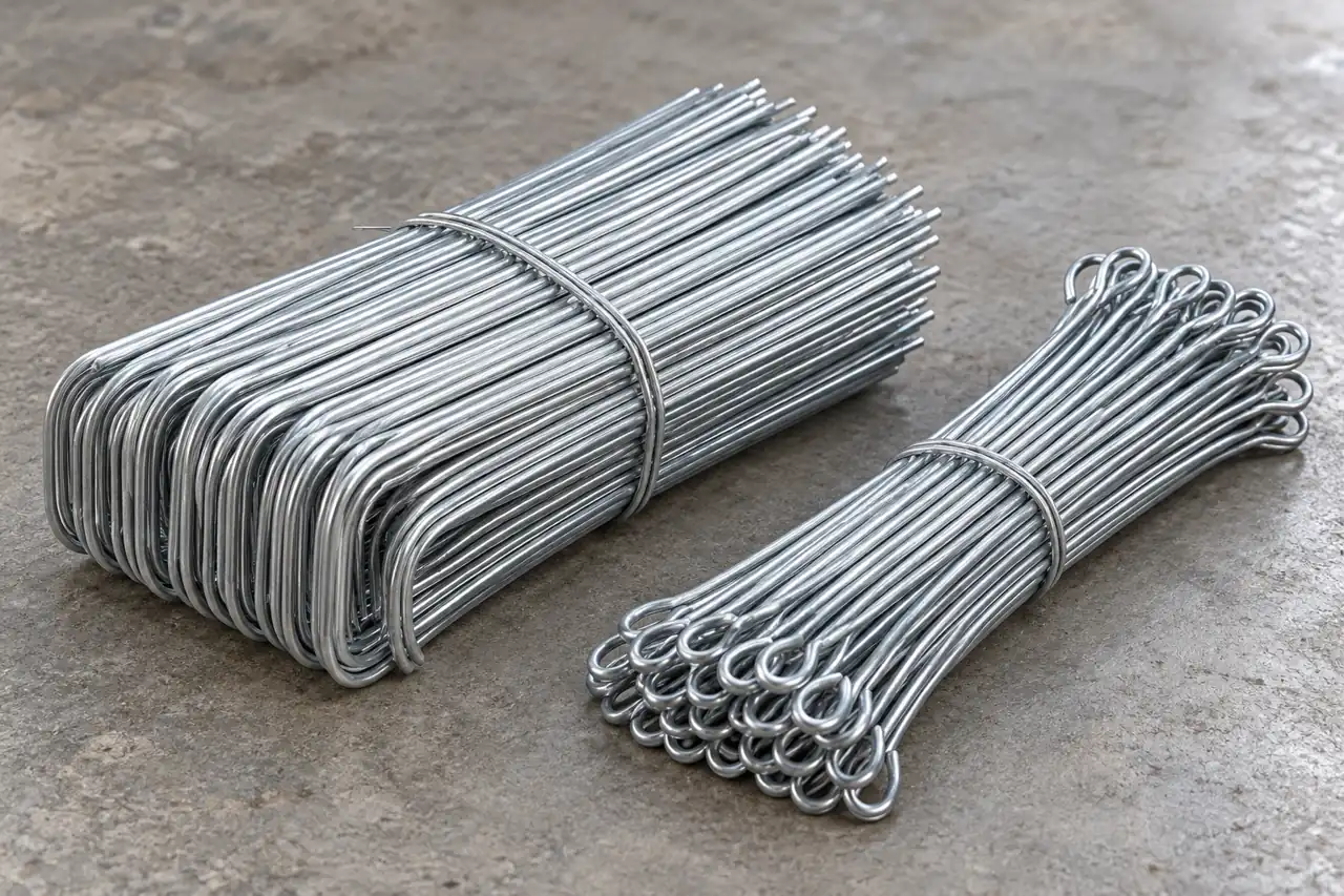
For construction buyers choosing preformed binding ties, select U-type geometry when free legs must wrap the joint and loop-ended ties when the installation tool engages defined loops. Specify the finished wire diameter, length, bend or loop dimensions, supplied condition and coating before comparing pack prices. Relia manufactures steel wire and can discuss the two listed finished-tie candidates by their actual supply scope. Validate reach, tool engagement, twist behavior and handling on the intended joint. Start with the rebar or bundle geometry and installation method; construction-use wording does not establish a structural tie capacity or a universal fit.
- U type tiesUse defined free legs and bend geometry where the tie wraps the joint.
- Loop ended tiesUse defined loops where the installation tool must engage and close the tie.
- Installation validationAssess reach, twist behaviour and handling on the actual joint and chosen method.
Selection context and decision detail
| Buyer requirement | Relia response | Evidence or condition |
|---|---|---|
| U or loop form | Discuss two listed finished-tie candidates | Joint reach and tool engagement must be defined |
| Core wire and coating | In-house drawing, annealing and galvanizing | Finished cutting/bending responsibility identified per offer |
| Acceptance evidence | Corresponding staged batch records available | Released dimensions and installation trial required |
Wire manufacture supports a separately defined finished tie
Connect confirmed core wire manufacture with the separately defined finished tie production and inspection responsibility.
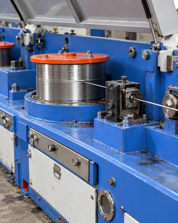
Relia's in-house wire operations comprise drawing, annealing and galvanizing. Incoming, process and final inspection are performed, with corresponding batch records available. For a finished U or loop tie, connect the core-wire identity with the offered cutting, bending and loop-forming responsibility. Our general wire scope does not by itself confirm every preforming operation in-house.
The selected offer should name the tie geometry and supplied surface route. Use the relevant batch evidence for that supply and agree the finished-form and installation checks needed by your construction programme.
- Wire stagesDrawing, annealing and galvanizing
- Finished formCutting, bending and loops allocated in offer
- EvidenceCorresponding staged batch records and finished checks
U-type and loop-ended listings define different starting choices
Specify exact released dimensions and diameter because a range or title does not define a finished tie.
Complete the prepared tie dimensions
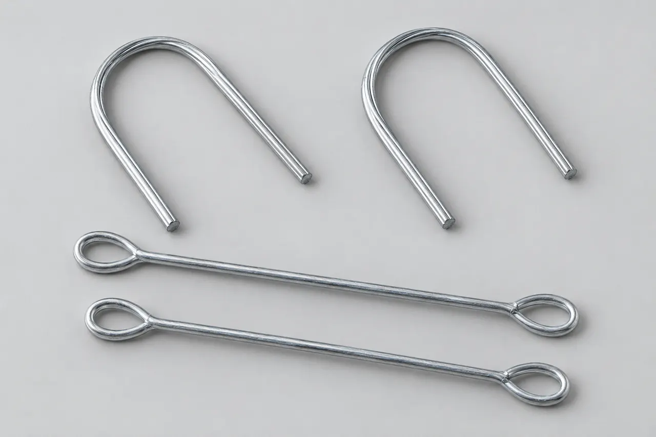
The U-type reference describes hot-dipped galvanizing, bending and cutting, with one selectable 0.5–1.5 mm diameter range. It still needs one exact diameter, leg length, bend radius and opening.
The electrogalvanized loop-tie reference has no actual diameter options; 0.35, 0.75 and 1.4 mm appear as requests in its title. Z110 and Z170 likewise need an agreed quantity and measurement basis. Specify loop size, closure, cut length and one core grade. Do not treat either broad listing as a fully dimensioned prepared tie.
- Exact wire sectionSelect one diameter and supplied condition rather than a broad enquiry range.
- Released U geometryDefine leg length, bend radius and opening after the wire is released.
- Released loop geometryDefine loop dimensions, closure and cut length needed by the installation tool.
Product references for your shortlist
Open the product details, then discuss the exact specification for your application.
Hot dip galvanized U ties
A candidate for prepared U shaped binding where exact diameter, released legs and bend geometry fit the intended joint.
Electrogalvanized loop ties
A candidate for tool engaged binding when finished loop geometry and coating acceptance are defined for installation.
Bending history affects the final closing operation
Preforming and the later bend or twist impose different demands on the same wire.
Preforming plastically bends the wire; the released shape also reflects elastic recovery. The subsequent installation bend or twist imposes further deformation, often at a previously worked location. A tight loop, sharp bend or damaged surface can therefore behave differently from a straight sample of the same wire.
Define finished geometry after release and inspect the locations that the tool loads. Record mechanical condition and any required bend or twist assessment on representative supplied ties. A tensile result from straight wire cannot alone establish the installed loop or twisted-joint result.
- Wire conditionGrade, diameter and forming state
- PreformBend/loop geometry after release
- InstallTool engagement and twisting demand
- AssessFinished joint and coating observations
Tool engagement needs a representative installation trial
Use the actual joint and tool to assess reach, engagement and the completed closing operation.
Evaluate the tie on its actual joint
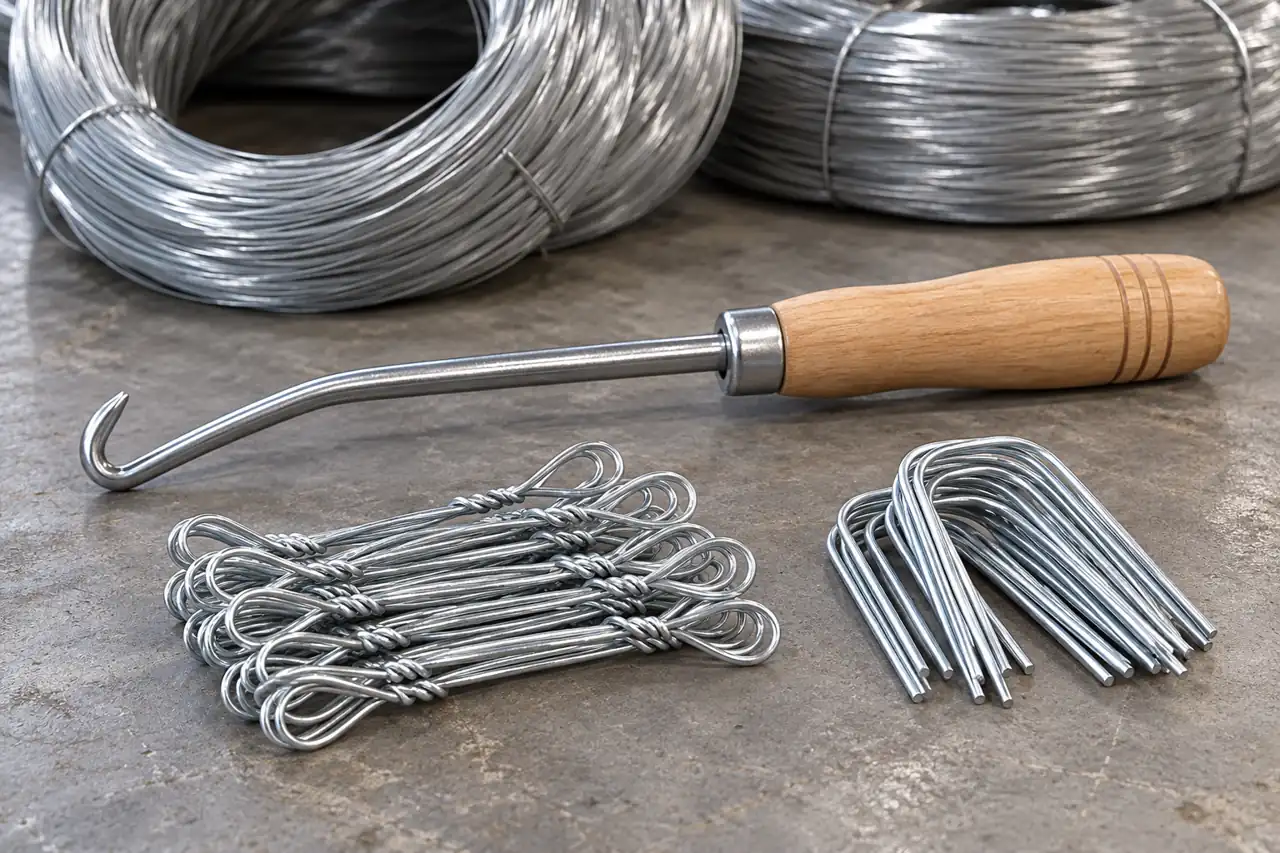
A loop that looks adequate on a bench may be too small for the tool hook or may open under the actual twisting sequence. A U tie can fail to reach around a joint or leave unequal legs that impede closing. Compare the tie against the intended bar/bundle dimensions and operator or automatic-tool method.
Record ease of placement, engagement, completed twist and sharp protruding ends using agreed criteria. The image is a tool-and-tie illustration; it supplies no tested joint strength or approved construction procedure.
- Place the tieCheck usable reach and leg or loop position around the intended bar or bundle.
- Engage the toolConfirm hook access and the actual manual or automatic closing sequence.
- Inspect the closureRecord completed twist, handling and sharp ends using the agreed installation criteria.
Coating quantity and retention are separate purchase requirements
Specify coating quantity and retention separately from fit, fracture and the galvanized surface description.
Hot-dip and electrogalvanized wording identify different surface-route descriptions; neither supplies a universal service life. Specify the required zinc basis and relevant evidence for the selected item. For a code such as Z110 or Z170, agree its meaning, units and whether it applies to the final wire or another defined basis.
Inspect coating after the representative forming and installation sequence. Bare areas, excessive flaking and damaged loops should be recorded independently from fracture or poor fit. The required acceptance method follows the actual product and project specification.
- RouteHot-dip or electrogalvanized description
- QuantityNamed zinc basis, units and result
- RetentionCondition after required forming
- ServiceProject-specific exposure, no universal life
A finished-form record makes incoming checks useful
Measure the finished released form and connect bundle samples with the relevant batch records.
Use a controlled tie drawing with overall length, leg or loop dimensions, wire diameter and the relevant limits. Define how the sample is supported and measured so a released U shape is not compared with a forcibly straightened one.
Link the sampled ties, bundle identity and corresponding batch records. Incoming checks can confirm the offered geometry and surface, while the site trial confirms installation behavior. Keep those roles distinct when a contractor or distributor accepts one bundle for a project.
- DrawingReleased shape and limits
- SampleActual supplied tie and bundle
- MeasurementsDefined support and locations
- TrialJoint and tool conditions recorded
Bundles should preserve geometry and size identity
Protect loops or legs in bundles and keep different sizes and coatings distinguishable.
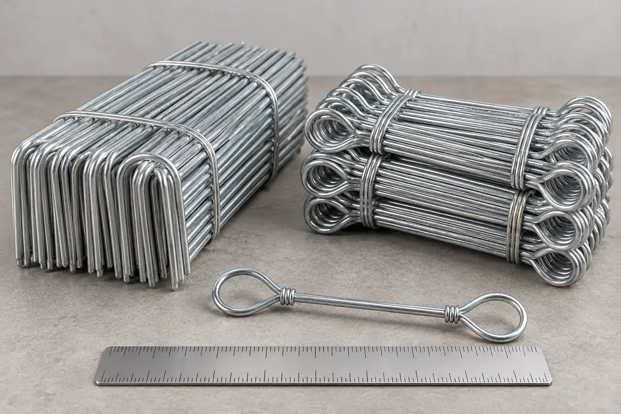
Preserve usable geometry through delivery
Preformed ties can distort when heavily compressed or mixed with another length. Agree a bundle unit and protection that preserve usable loops or legs during transport and unloading. Separate different diameters, lengths and coating specifications in the packing-list scheme.
The ruler and plain bundles shown are AI-assisted form illustrations. They do not document an actual shipment count or measurement. Custom labels, pack sizes and mixed project deliveries need confirmation in the quotation rather than being assumed from a generic packing photograph.
- Bundle protectionChoose a unit and protection that avoid distorted loops or legs during transport.
- Variant separationKeep diameter, length and coating requirements distinguishable after packages are opened.
- Receiving referenceRetain bundle identity and measure released samples against the accepted tie drawing.
Failure observations distinguish material and installation causes
Use failure location, unused ties and installation details to distinguish material from geometry or tool problems.
A fracture at a loop, a hook that cannot engage and coating damage call for different checks. Retain the failed tie with an unused sample, the joint geometry and the tool setting or operator sequence. Review supplied geometry, condition and local surface damage before simply increasing diameter.
For repeat supply, retain the accepted drawing and installation reference. Review changes in wire grade, diameter, coating route or preformed geometry so the next bundle is compared with the reason for approval.
- ObserveLocation and type of fault
- RetainUnused tie, failed tie and lot
- SeparateGeometry, condition, coating and tool causes
- ApproveRevised supply or installation decision
Prepare the joint and closing tool brief
Send the joint and tool reference with the exact prepared geometry for a coherent offer.
Show us the joint and the tool or method used to close it. We can review the prepared tie candidate and clarify geometry, evidence and bundle requirements.
Qingdao Relia Industries Co., Ltd.
Contact address: Shuyuan Road, Qingdao, Shandong, China
- Joint sketch and installation method
- Required U or loop form
- Exact diameter and released dimensions
- Coating and tool engagement requirements
- Trial quantity and bundle unit
Enquiry scope and supporting detail
Send a sketch of the joint or bundle, required U or loop form, exact wire diameter, released dimensions and coating requirement. Include the tool/hook reference, installation method and the failure or handling problem to prevent. Add trial quantity, preferred bundle unit and destination.
We can discuss the relevant wire manufacturing scope, the finished-tie supply responsibility and corresponding batch evidence. Request one coherent offer with the selected geometry, inspection and packing scope; sample arrangements and commercial conditions are agreed for that item.
- Tie definitionShape · diameter · finished dimensions
- Use trialTool or method · representative workpiece
- OrderQuantity basis · packing · destination