
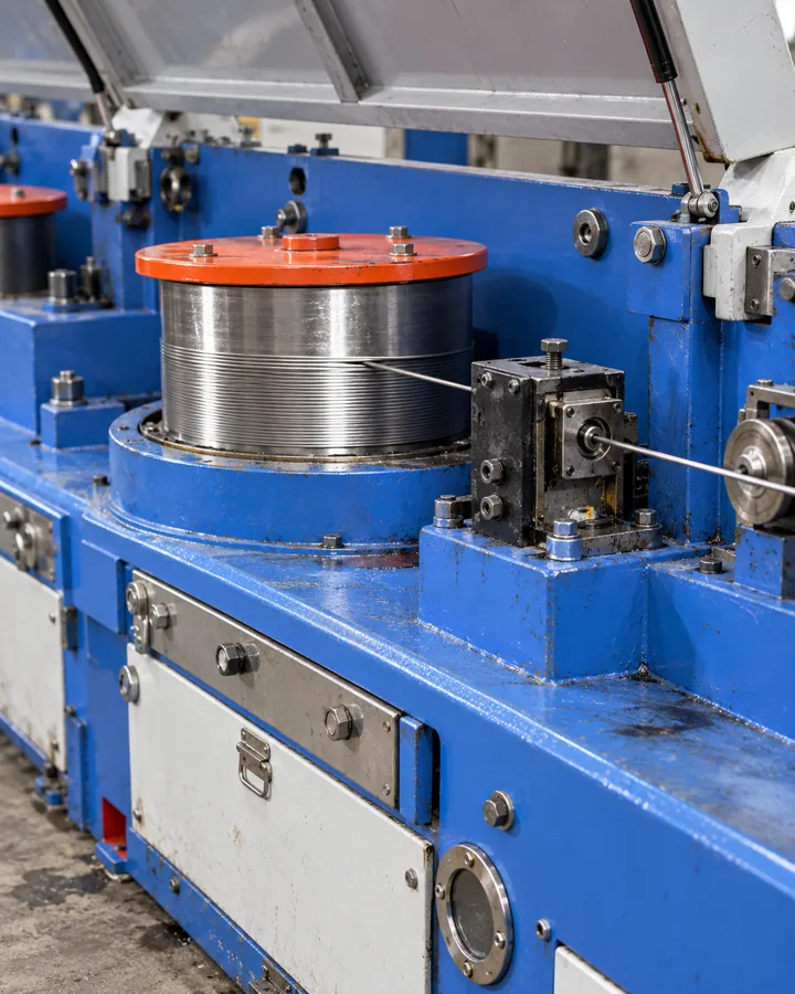
Flat Binding Wire for Automatic Feeding and Tying
Choose flat binding wire as a complete section and supplied condition that can feed in the right orientation and close an acceptable tie. Width, thickness, edges and coil presentation work together. This guide helps you trace guide faults, springback and coating loss so the trial approves both the incoming wire and the actual tying result.
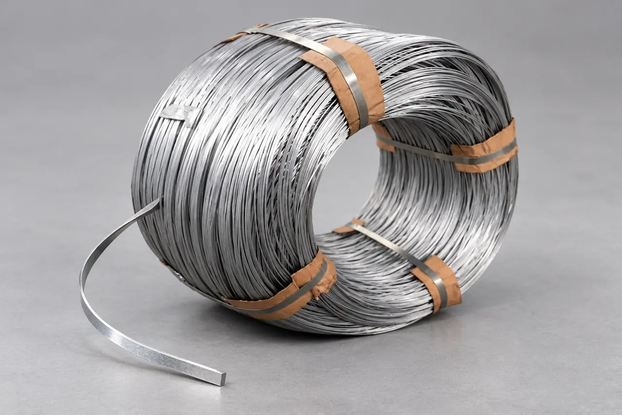
Define the wire the tying head needs
For a packaging or tying line using flat galvanized wire, specify width, thickness, edge condition and supplied temper before selecting a catalogue size. The rectangular section must pass the guides in the intended orientation, bend through the tying head and leave an acceptable joint without excessive springback or coating loss. Relia manufactures steel wire with drawing, annealing and galvanizing in-house. Our flat-wire listing can start the discussion, but its diameter-style options do not define a complete flat section. Send the machine's wire drawing, payoff arrangement and failed tie so the offered section and trial address the actual feeding and closing duty.
- Flat sectionSpecify width, thickness and edge condition for the actual guide geometry.
- Supplied conditionSet the required material and forming behaviour for closing the accepted tie.
- Feed presentationDefine orientation and payoff format before testing the complete tying path.
Selection context and decision detail
| Buyer requirement | Relia response | Evidence or condition |
|---|---|---|
| Guide-compatible flat section | Discuss a defined steel-wire offer | Width, thickness, edges and orientation required |
| Forming condition | In-house drawing, annealing and galvanizing | Selected sequence and joint trial remain product-specific |
| Batch evidence | Incoming, process and final records can be provided | Connect record and sample to the offered coil |
Wire processing and inspection need a section-specific order
Connect the ordered flat section with Relia wire operations and product specific inspection evidence.
Relia manufactures steel wire and operates drawing, annealing and galvanizing in-house. Incoming, in-process and final inspection are performed; the corresponding batch records can be provided. For flat binding wire, link the ordered grade and supplied condition to width, thickness and coating acceptance rather than relying on a gauge word.
Our general wire operations do not establish one particular flattening route, edge radius or tying-machine approval. The offer should identify the selected section-development sequence and final condition, with the required measurements and forming evidence for that product.
- Wire manufactureDrawing, annealing and galvanizing in-house
- Selected flat sectionWidth, thickness, edges and supplied condition
- Inspection evidenceCorresponding incoming, process and final batch records
The listing leaves width and thickness to be resolved
Use a finished section drawing rather than treating a diameter style option as a rectangular specification.
The galvanized binding-wire reference is described as Flat Wire and gives Q195, Q235, SAE1006 and SAE1008 alternatives. Its actual menu nevertheless uses Diameter labels: 1.8, 2, 2.5, 3, 5, 8 and 10 mm. The title's BWG20/21/22 wording is not a ready-made rectangular width-by-thickness schedule.
Select one steel grade and a drawing of the finished section. State whether dimensions include zinc, the permissible variation along the coil and the required edge condition. The catalogue provides no numerical strength, hardness or zinc-quantity acceptance for the selected flat wire.
- Flat identityWidth × thickness with coated basis
- Diameter menu1.8 / 2 / 2.5 / 3 / 5 / 8 / 10 mm labels
- Material choiceOne selected Q195/Q235/SAE1006/SAE1008 basis
- AcceptanceNumerical section, mechanics and coating to agree
Product references for your shortlist
Open the product details, then discuss the exact specification for your application.
Galvanized flat binding wire
A candidate for automatic tying when the actual rectangular section, condition and coil format are defined by the feeder.
Section orientation changes bending and guide contact
Section orientation changes bending and guide contact, so inspect the actual path through the machine.
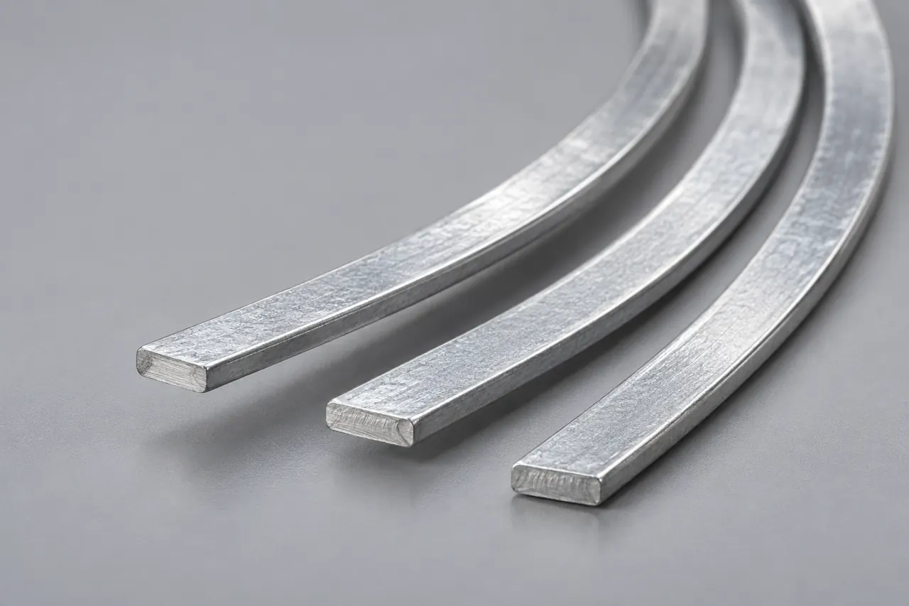
Read section and orientation together
A rectangular wire has different bending stiffness about its two axes. A feed path that turns the strip onto its edge can therefore produce a different forming load even when its cross-sectional area is unchanged. Elastic recovery after bending also changes the released tie geometry; supplied condition and bend demand must be assessed together.
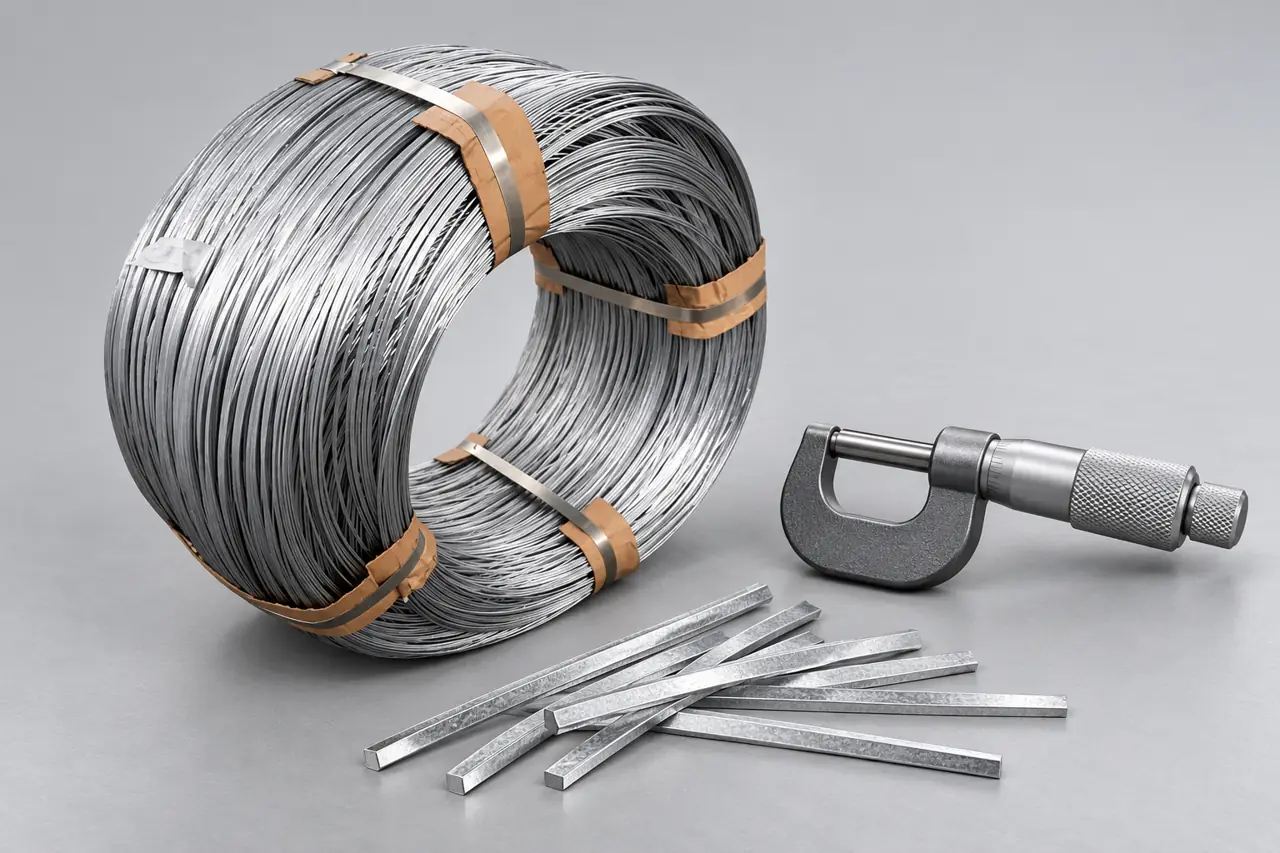
Measure width and thickness at agreed locations and inspect edges for burrs or damage that can scrape guides or initiate cracking. Trial the intended orientation through the actual guide and closing path. The sample image illustrates section geometry; it does not certify an edge radius or tolerance.
- Width and thicknessMeasure the two dimensions and their variation on the same trial wire.
- Working orientationCheck how the rectangular section turns through guides and the closing path.
- Edge conditionInspect burrs or damage that can scrape guides or initiate local cracking.
Drawing and annealing affect the closing response
Choose delivered condition for the required closing response instead of relying on the word soft.
Cold drawing changes section and deformation history. A more work-hardened condition can resist the next bend and increase springback; annealing changes the material condition for subsequent forming. The correct target is a defined combination of strength and ductility that survives the closing operation and retains the required tie, not simply the word soft.
Connect section readings, mechanical results and the stated supplied condition to the same trial coil. Then inspect the actual bend or twist location. A wire tensile result alone cannot establish the strength of the machine-made joint.
- Cold deformationSection and work history change
- ConditioningRequired forming condition is selected
- Wire evidenceSection and mechanics linked to the coil
- Joint trialGuide path, bend and released tie assessed
Payoff can cause feeding faults without a material change
Investigate cast, winding and payout before attributing every feed fault to wire material.
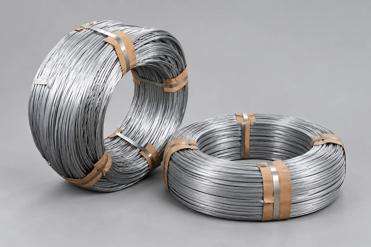
Trace a feeding fault to its source
Coil cast, helix, winding arrangement and payout direction affect the wire presented to the guides. Package distortion or crossovers can introduce tension spikes and twist the flat section. Separate these effects from a section or temper change when the line starts misfeeding.
Specify the coil opening, outside envelope, unit mass and intended payoff method. Observe representative portions of the coil and record stops or guide marks with their position. The two illustrated winding arrangements explain the packaging decision; they are not a promise that either fits every feeder.
- Observe the packageReview winding, payout direction and any distortion in the selected coil format.
- Locate the eventConnect stops or guide marks with the actual position in the coil.
- Compare the wireDistinguish package effects from changes in flat section or delivered mechanical condition.
Zinc retention and clean feeding require separate checks
Read coating quantity, retention and clean feeding as separate acceptance requirements.
Galvanizing protects the steel surface, but zinc quantity and adhesion under deformation answer different questions. A bright coil can still shed coating at a tight bend. Debris created in the feeding path may affect guides even when the wire itself remains unbroken.
Use the selected applicable wire/coating specification and agreed methods. ASTM A641/A641M's regular-coating category has no specified minimum zinc mass, so a minimum requirement must be stated explicitly where applicable. Record coating appearance, required quantity and retention after the representative tying operation independently.
- Coating identityApplicable route and specification
- QuantityRequired zinc basis and result
- RetentionObserved behavior at the critical bend
- Clean feedDebris and guide condition recorded
Failure location identifies the next variable to investigate
Use the location and type of failure to choose the next material or machine check.
A crack at the closing bend suggests a different investigation from a jam at the first guide. Record whether the symptom is edge scoring, rotational misfeed, fracture, a loose joint or coating debris. Preserve the failed length with its coil identity and the machine setup.
Compare width/thickness variation and supplied condition before changing guide settings and tension simultaneously. A trial should leave an explainable operating window and joint acceptance result. The matrix below is a diagnostic starting point, not a claim that a particular supplied batch has these defects.
- First-guide jamSection orientation, package and guide clearance
- Closing crackBend demand, edge condition and temper
- Loose tieSpringback, closing setup and joint geometry
- DebrisCoating retention and guide contact
An approved tie needs linked material and line records
Retain wire and line records together while keeping incoming conformity separate from finished tie acceptance.
Keep the accepted wire and tie connected
Retain the actual flat-wire sample with its section drawing, grade, supplied condition and relevant batch inspection records. Add guide setup, closing sequence, line speed and the test used to accept the finished tie. The micrometer in the illustration is at rest; no measured section or tie performance is shown.
For replenishment, carry that approved revision into the order. Review changes in section, coating, condition or coil arrangement before introducing them to the line. Keep incoming wire conformity separate from the downstream joint result.
- Material referenceRetain section drawing, grade and supplied condition with the approved wire sample.
- Line conditionRecord guide setup, orientation and closing sequence used in the representative trial.
- Tie acceptanceKeep the joint test and result separate from incoming wire conformity records.
Define the feeder section and closing result
Send the feeder geometry, wire orientation and tie acceptance to define the product specific trial.
Share the feeder drawing and a representative tie or failure. We can discuss the actual wire section, supplied condition and coil format needed for the line comparison.
Qingdao Relia Industries Co., Ltd.
Contact address: Shuyuan Road, Qingdao, Shandong, China
- Width thickness and edge limits
- Material and coating acceptance requirements
- Guide drawing and wire orientation
- Coil envelope and payoff method
- Closing geometry and tie acceptance
Enquiry scope and supporting detail
Send width and thickness limits, grade or current material reference, required coating and the tying-head or guide drawing. Include coil/payoff dimensions, the wire orientation through the machine, the closing geometry and any failed sample or stoppage record. State how the finished tie is accepted and the quantity needed for a representative line trial.
Request the offered section, supplied condition, relevant batch records and pack arrangement together. We can discuss the wire-manufacturing scope and the product-specific trial; commercial quantity, sample arrangements and schedule are confirmed in the individual quotation.
- SectionWidth · thickness · edges · material
- FeederGuides · coil support · payoff
- Trial and orderQuantity · acceptance · packing