
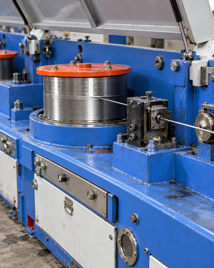
Stainless Wire Feedstock for Further Drawing
Specify stainless drawing feedstock around the reduction your line must perform and the final wire you need. This guide connects inlet diameter and delivered condition with work hardening, surface preparation and payoff. It helps you plan an identified drawing trial that locates breaks or scoring without changing material and tooling at the same time.
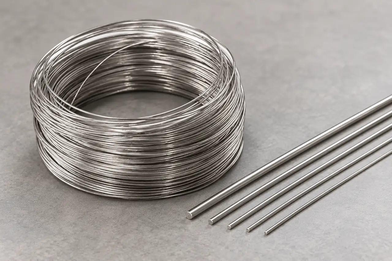
Work back from the final wire
If you draw stainless wire further, buy the feedstock around the next reduction and final wire requirement rather than brightness alone. Start with one alloy, actual inlet diameter and delivered mechanical condition, then match surface preparation, lubrication and payoff to your line. Relia manufactures steel wire with drawing and annealing in-house, while the selected stainless route still needs definition. Send inlet/outlet sizes, required final properties and a representative breakage or surface example so the offer can support an identified drawing trial and meaningful acceptance records.
- Final requirementDefine the target diameter and properties needed after your additional drawing.
- Inlet selectionSpecify actual alloy, inlet diameter and delivered mechanical and surface condition.
- Drawing trialConnect the identified input with the intended reduction sequence and observed output.
Selection context and decision detail
| Buyer requirement | Relia response | Evidence / condition |
|---|---|---|
| Drawable inlet material | Steel-wire manufacture with drawing/annealing | Selected stainless alloy and delivered condition |
| Controlled next reduction | Route and line-interface review | Actual inlet/outlet areas, surface and payoff |
| Traceable trial | Incoming/process/final QC and batch records | Input condition separate from further-drawn output |
Drawing and annealing scope should follow the selected stainless wire
Define the selected stainless route and delivered state within the confirmed wire drawing and annealing scope.
Relia manufactures steel wire and operates drawing and annealing in-house. Incoming, in-process and final inspection are performed, with corresponding batch records available. For stainless feedstock, agree the actual alloy, delivered state and process responsibility; this does not confirm every grade-specific annealing atmosphere, thermal route or mechanical value.
Products 757/758 offer round stainless wire, including a broad 0.3–26 mm range and selected individual diameter entries. The 0.15 mm title request is not an actual option. These support a precise enquiry, not a verified inlet condition for every drawing line.
- IncomingRequired feedstock form and diameter
- ProcessYour preparation and drawing route
- OutputTarget finished-wire requirement
Area reduction is the useful geometric comparison
Use area reduction to compare inlet and outlet geometry rather than the diameter change alone.
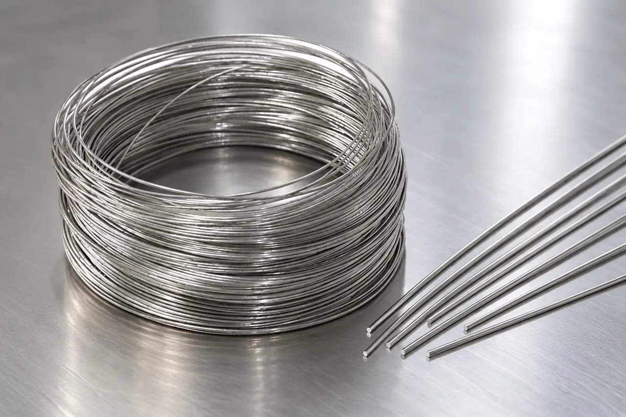
Compare section change on an area basis
For round wire, area reduction is 1 − (outlet diameter/inlet diameter)². A 2.0 to 1.6 mm change therefore represents 36% area reduction. This is a geometry example, not a recommended pass or a confirmed production capability.
Use actual measured inlet and target sizes when reviewing the route. Equal diameter changes at different starting sizes do not produce equal area reductions.
- Input diameterUse the actual measured round-wire inlet diameter for the geometry calculation.
- Output diameterUse the target diameter rather than comparing absolute diameter changes alone.
- Reduction exampleThe stated 2.0 to 1.6 mm example is 36% area reduction, not a pass recommendation.
Product references for your shortlist
Open the product details, then discuss the exact specification for your application.
Bright stainless wire for drawing review
A candidate when selected alloy, inlet diameter and delivered condition can be defined for a further-drawing trial.
304 or 316 stainless drawing feedstock
A broad stainless-wire candidate to narrow to one grade and physical condition for the intended reduction route.
Cold work changes the condition needed by the next pass
Specify incoming mechanical condition separately from the final properties required after your additional drawing.
Drawing plastically reduces the section and work-hardens the material. Annealing can restore deformation capacity, but its appropriate route depends on alloy and the required final state. The incoming condition therefore affects more than whether a wire fits the first die.
Specify represented tensile/ductility requirements where needed, and distinguish those from the final wire properties after your additional drawing.
- AlloyActual material designation and records
- ConditionSupplied mechanical and surface requirement
- DiameterConfirmed size and measurement basis
Surface defects and lubrication can interact in the die
Review inlet surface and lubrication together because both can affect scoring, pickup and breaks at the die.
A surface discontinuity, embedded contamination or unsuitable lubricant condition can contribute to scoring, pickup or breaks during drawing. Define the supplied surface and any preparation responsibility, then inspect the inlet and output along the affected length.
A bright finish cannot establish defect depth, cleanliness or lubricant compatibility. Retain actual samples rather than judging only a coiled-wire photograph.
- Inspect the inletRetain actual feedstock showing discontinuities, contamination or the selected surface condition.
- Record die conditionsKeep preparation and lubrication observations with the relevant drawing stage and material position.
- Compare the outputLocate scoring, pickup or breaks against the identified inlet and operating record.
A trial should connect the break to its position and setup
Locate defects by material position and drawing stage while retaining the actual tooling and operating baseline.
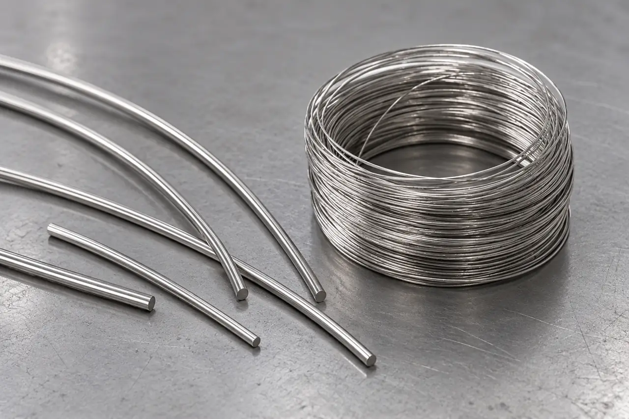
Locate the defect within the drawing run
Run identified feedstock through the intended reduction sequence and retain the relevant die/lubrication and operating conditions. Locate breaks or surface change by stage and material position. Compare inlet dimensions/condition with the drawn output.
Do not change alloy, input condition and tooling together when investigating a defect. One successful short sample does not establish unlimited continuous performance.
- Material positionIdentify where the break or surface change occurred along the supplied wire.
- Drawing stageRecord the reduction stage, die and lubrication conditions at that location.
- Input comparisonCompare retained inlet material and output before changing several variables together.
Payoff and winding influence stable material delivery
Define winding and payoff interfaces so feeding interruptions are not confused with a material defect.
Define coil or spool dimensions, winding, permitted joints and handling limits for the actual line. A tangle, kink or interrupted feed can produce a break that is not caused by the stainless chemistry.
The coil and straight-sample illustrations show product form; they are not a pass schedule, actual tensile result or promise of a specific package.
- Package interfaceDefine coil or spool dimensions and handling limits for the actual payoff.
- Winding and jointsSpecify winding presentation and permitted joints before loading the supplied package.
- Interrupted deliveryRecord tangles, kinks and feed stops before attributing a break to alloy identity.
QC records should preserve inlet and output conditions separately
Keep supplied inlet records and your downstream drawing-trial results as connected but separate evidence.
Link actual alloy, inlet diameter/roundness, delivered mechanical state and surface checks to the supplied lot. Keep the subsequent drawing trial as separate evidence of behavior under its recorded route.
Agree relevant methods and record representation through the confirmed QC stages. No universal test frequency, instrument, spring qualification or welded-wire assembly capability is implied.
- Supplied materialLink actual alloy and delivered mechanical state with the represented feedstock lot.
- Inlet geometryRetain inlet diameter, roundness and agreed surface-check results for that supply.
- Drawing trialKeep output behaviour and operating conditions as separate evidence of the downstream route.
Protected coils should retain the approved feedstock identity
Protect coil condition and preserve approved alloy, diameter and delivered state through receiving and reorders.
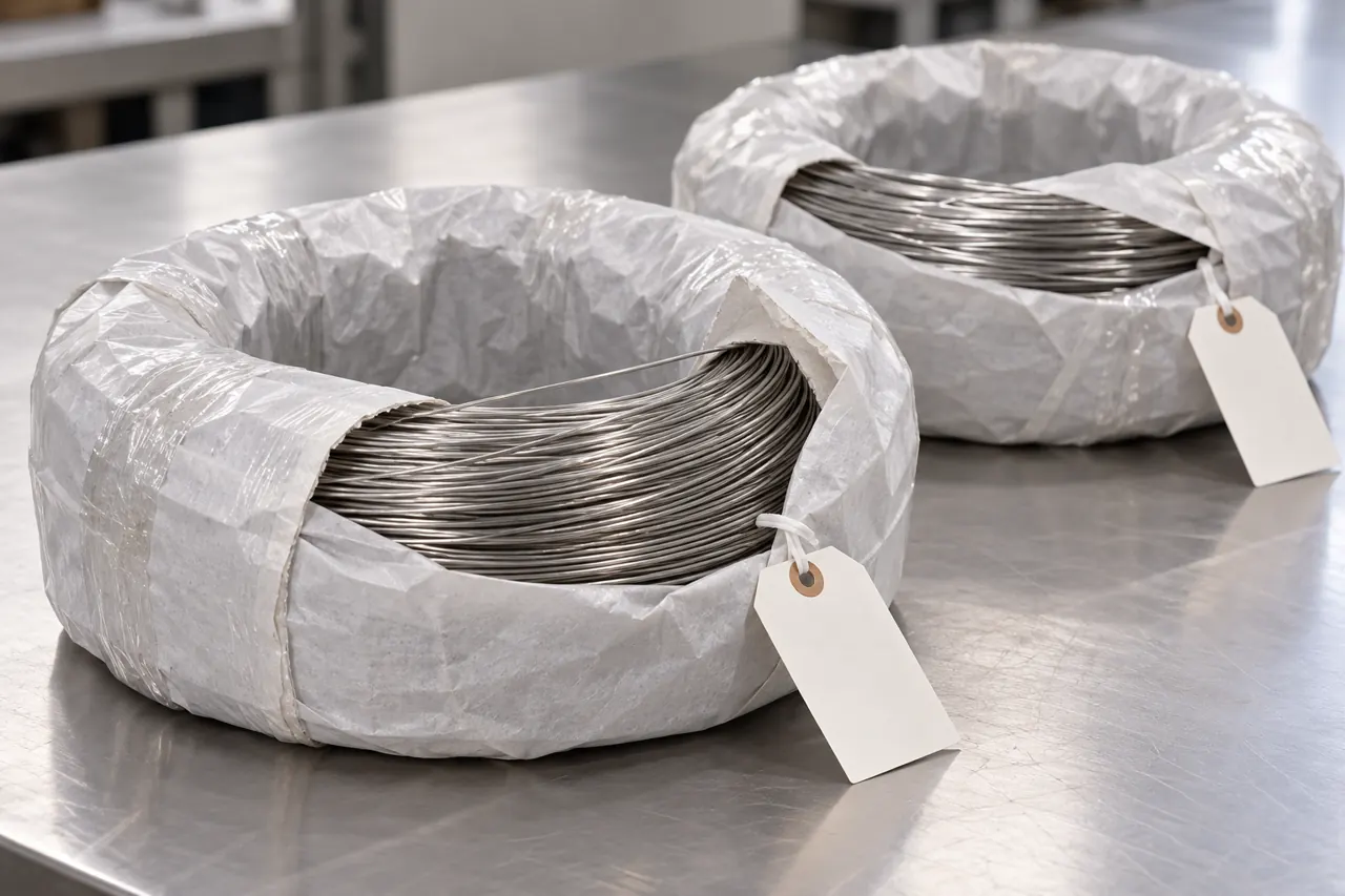
Preserve the qualified feedstock through receipt
Check package damage, surface condition, winding and lot identity before payoff. Keep identification connected to retained samples and the accepted trial. Where a discrepancy appears, preserve the package and affected material context.
Repeat orders should retain alloy, inlet condition, actual diameter, surface and feed format. Similar brightness does not authorize a different grade or annealing state.
- Package conditionCheck damage, exposed surfaces and winding before loading the payoff system.
- Retained identityKeep coil references connected with samples and the accepted trial record.
- Repeat baselinePreserve alloy, inlet diameter, condition and feed format on subsequent offers.
Prepare the inlet and final-wire brief
Send actual inlet and target requirements so the feedstock proposal supports a representative drawing trial.
Share the next drawing route and the wire properties your process must deliver. We can review a specific inlet condition and the evidence needed for a useful trial.
Qingdao Relia Industries Co., Ltd.
Contact address: Shuyuan Road, Qingdao, Shandong, China
- Selected alloy and inlet diameter
- Target diameter and mechanical requirements
- Intended reduction and preparation route
- Lubrication and surface acceptance
- Payoff limits and problem samples
Enquiry scope and supporting detail
Send selected alloy, actual inlet and target diameters, required inlet/final mechanical acceptance and intended reduction sequence. Include surface/lubrication needs, payoff limits and representative problem samples. We can then define a stainless feedstock offer and controlled trial, with process responsibility, batch evidence and commercial conditions stated.
- IdentityWire or rod form, alloy and diameter
- RoutePreparation, drawing and target condition
- SupplyPackage limits, sample and required records