
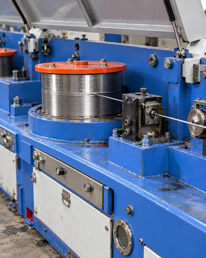
Narrow Steel Strip Feedstock for Stamping Production
For stamping, choose narrow strip around the die, guides and payoff arrangement rather than coil price alone. This guide helps you specify actual gauge, width, camber and slit-edge condition, then separate incoming defects from tool-generated burrs. Use a representative part trial to connect the strip offer with stable feeding and accepted components.
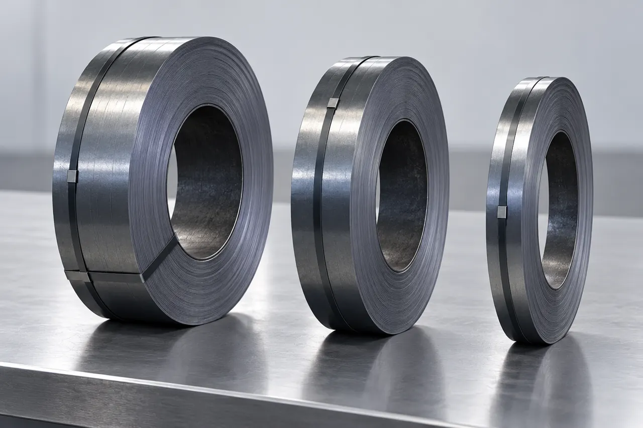
Define strip from the press-line interfaces
If a stamping line wastes narrow strip through tracking errors, burrs or inconsistent parts, start with the strip-to-die interface rather than the cheapest coil price. Choose carbon or stainless steel from the part's material requirement, then define actual thickness, slit width, edge condition and payoff limits. Relia manufactures plate and coil with selected rolling in-house; slitting and edge preparation still need a specific responsibility. Send the die feed layout and an acceptable part so the offered strip can be checked through a representative production trial.
- Part materialSelect the grade and condition required by the actual stamped component drawing.
- Strip geometrySet gauge, slit width and edge condition against die and guide requirements.
- Payoff packageMatch coil dimensions and winding with the receiving and feed equipment limits.
Selection context and decision detail
| Buyer requirement | Relia response | Evidence / condition |
|---|---|---|
| Stable die input | Plate/coil manufacture and rolling review | Actual material, gauge and tooling baseline |
| Usable slit edge | Finishing scope assigned per order | Width, camber, burr and direction defined |
| Traceable trial | QC stages and batch records | Slit coil linked to material and accepted part |
The offer should distinguish rolling from slit-strip preparation
Assign slitting and edge preparation separately from the selected in-house rolling route and its corresponding batch evidence.
Relia performs hot or cold rolling in-house for the selected steel plate/coil product. Incoming, in-process and final inspection are performed and corresponding batch records can be provided. Slitting, edge finishing and final coil arrangement require an order-specific scope; rolling ownership does not prove every finishing step.
The carbon listing offers 0.2–4, 4–60 and 60–115 mm categories, so its title's 0.12 mm request is unconfirmed. The stainless reference describes 0.3–3.0 mm and custom thickness, despite thicker title requests. Neither supplies your final narrow-strip width.
- Selected rollingRelia performs the selected steel rolling route with corresponding staged inspection and batch records.
- Slitting and edgesDefine who performs slitting and edge finishing for the actual narrow-strip offer.
- Final coilAgree the actual gauge, slit width and coil arrangement rather than broad catalogue thickness categories.
Thickness is a tooling input as well as a product dimension
Define actual thickness and limits because gauge changes the tooling-clearance relationship and the resulting part dimensions.
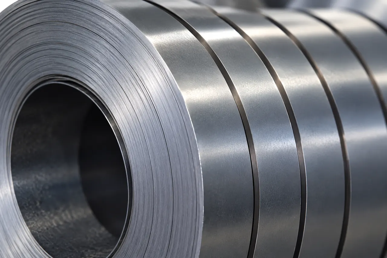
Connect thickness control with the stamped part
Strip thickness changes the clearance relationship at a punch and die and affects formed-part dimensions. Define nominal thickness, variation limits and measurement basis for the selected material. A custom label does not remove the need to confirm an actual gauge.
Retain a flat input sample with the accepted stamped part so dimensional drift can be traced to material, setup or tool condition.
- Actual gaugeSpecify nominal thickness and variation limits for the selected grade and condition.
- Tooling relationshipReview the gauge against the die setup used for the actual part trial.
- Retained comparisonKeep a flat input sample with the accepted stamped component and recorded setup.
Product references for your shortlist
Open the product details, then discuss the exact specification for your application.
Carbon-steel strip feedstock enquiry
A carbon-steel reference for a defined rolling condition, actual gauge and slit-strip package evaluated on the stamping line.
Stainless strip feedstock enquiry
A separate stainless reference when the part requires an identified stainless grade and supplied condition for stamping or forming.
Slitting creates an edge that needs its own acceptance
Set incoming edge and burr acceptance independently from burrs created later by the stamping die.
A slit edge can carry rollover, fractured surface and burr. Knife setup, material condition and tool wear influence the result. Specify the permitted edge condition, burr direction and measurement method where the strip contacts a guide or the edge enters a bend.
Burr height on incoming strip and burr on a newly punched feature are different observations; the second can arise from the downstream die.
- Input edgeBurr, direction and edge condition
- FeedWidth, camber and guide setup
- Cut featureTool clearance and wear
- Formed partMaterial condition and bend geometry
Width and camber influence the feed path differently
Measure width and camber separately because correct local width cannot establish straight tracking along the strip.
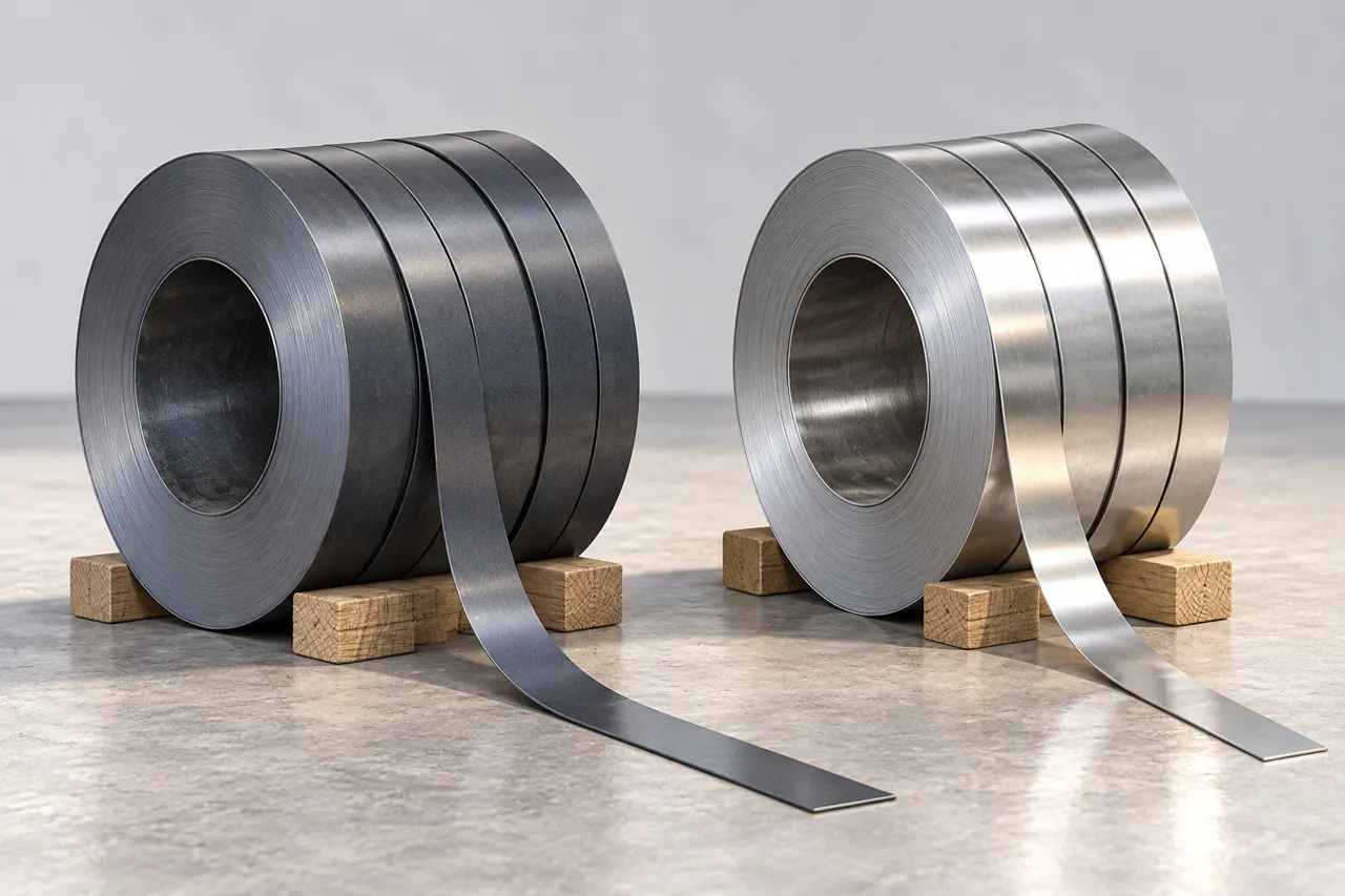
Width and camber answer different feed questions
Width governs guide clearance and available nesting width. Camber is lateral curvature along the strip, which can challenge tracking even where local width is correct. Define the evaluation length and relaxed condition rather than pulling a short sample straight by hand.
The coil photographs compare narrow product forms; they do not demonstrate an accepted edge or camber result.
- Local widthCheck guide clearance and available nesting width at the agreed measurement locations.
- Longitudinal camberAssess lateral curvature over a defined length with the strip in its stated condition.
- Feed observationsRecord tracking and guide behavior without pulling a short sample straight by hand.
Payoff compatibility should be checked before the trial
Match bore, envelope and winding to the actual decoiler, recording leveling and feed settings during evaluation.
Specify bore, outside envelope, handling limits and winding arrangement for the actual decoiler. Coil set and support during unwinding can influence feeding, so record the leveling and feed setup used for evaluation.
A strip that fits a pallet may still exceed the line interface. Keep mandatory equipment limits distinct from optional package preferences.
- Decoiler interfaceSet bore, outside envelope and handling limits against the actual receiving and payoff equipment.
- Winding and supportAgree winding and unwinding support where they influence coil set and feed behavior.
- Trial setupRecord leveling and feed conditions, keeping mandatory equipment limits separate from package preferences.
A stamping trial should isolate the source of a defect
Retain material, lubrication and tool conditions to distinguish incoming edge faults from registration, cutting or forming problems.
Run identified strip with the intended lubrication, feed, tool and part geometry. Inspect input edge condition, registration, cut features and formed bends separately. When comparing lots, retain setup and tool condition so the comparison does not confuse worn tooling with material variation.
No fixed punch clearance or guaranteed die life follows from this guide; the actual die and material need their own qualified setup.
- IdentifyCoil and supplied condition
- RecordTool, feed and lubrication
- SeparateInput edge versus stamped features
- RetainAccepted part and setup
Coil identity should survive splitting and packing
Connect slit coils to parent material and represented edge results while protecting identity through splitting and packing.
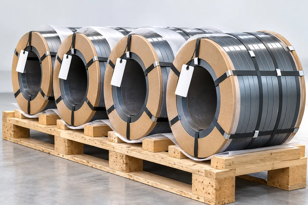
Preserve identity as parent material becomes slit coils
Ask how parent material identity follows the supplied slit coils and which dimensional or edge results are represented by each record. Packaging should protect edges and keep coil identification available after unloading.
Blank tags in the illustration show identification locations, not a promise of a particular barcode system or traceability software.
- Parent referenceAsk how the source material identity follows each supplied narrow-strip coil.
- Represented resultsIdentify which dimensional and edge checks apply to the actual coils delivered.
- Protected edgesAgree packing that protects slit edges and keeps coil identity available after unloading.
Repeat supply needs the accepted strip and tool baseline
Repeat the approved material and strip geometry with the accepted tooling baseline, using the same measurement basis.
Preserve selected alloy/grade, rolling condition, thickness limits, width, edge and coil envelope with the accepted trial. A shiny stainless strip is not a substitute for carbon steel, and a changed stainless grade can alter fabrication response.
Use the same measurement basis when investigating a later feed or part-quality change.
- ApproveStrip dimensions, edges and feed trial
- CompareFirst repeat lot and delivered coil format
- ReviewMaterial, processing and line changes
Define the strip-to-die interface
Send the strip, feed and part references together to define finishing responsibility and a meaningful stamping trial.
Share the part and feed references with current defects so we can discuss a strip condition and trial that distinguish input variation from tooling effects.
Qingdao Relia Industries Co., Ltd.
Contact address: Shuyuan Road, Qingdao, Shandong, China
- Selected material and rolling condition
- Actual gauge and variation limits
- Slit width camber and edge acceptance
- Coil bore envelope and winding
- Critical part and retained trial reference
Enquiry scope and supporting detail
Send selected material and condition, actual gauge, slit width, edge/burr requirement and the payoff envelope. Add critical part features, the intended operation and the retained trial evidence you need. We can then define rolling and finishing responsibility, batch records and a practical acceptance trial before quantity and delivery terms are agreed.
- StripGrade, condition, thickness and slit width
- EdgeAcceptance method and any extra preparation
- LineCoil limits, winding and trial requirement