
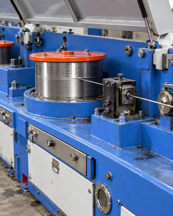
Decorative Stainless Tube for Railings and Display Frames
For railings and display frames, choose stainless tube by its service environment, section geometry and finished appearance. This guide helps you specify exposed faces and fittings, then approve a representative bend or welded joint. Keep the material and finish decision connected to the project design and the actual role of the assembly.
Specify the tube around the complete assembly
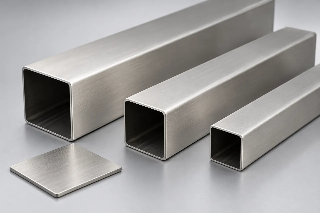
For railings and display frames, choose decorative stainless tube by exposure, section geometry and the final visible surface—not polish alone. A lightly loaded display and a safety-critical balustrade need different design acceptance. Relia's 202 rectangular-tube listing is a starting reference; specify the engineer-selected alloy, actual section and finish before approving it for either job. Match a fabricated sample, including joints, to the appearance brief, and keep structural or fixing approval with the project designer. Send the drawing and cleaning environment so the tube offer has a clear scope.
- Service environmentDescribe outdoor exposure, cleaning and maintenance conditions that influence the selected alloy.
- Section and fittingsSet actual geometry and joint interfaces against the frame or railing drawing.
- Final appearanceApprove the finish after the representative bending, joining and blending operations.
Selection context and decision detail
| Buyer requirement | Relia response | Evidence / condition |
|---|---|---|
| Drawing-matched tube | Seamless/welded steel-pipe manufacturing | Selected alloy, actual section and route |
| Controlled visible surface | Finish and fabricated-sample review | Direction, joints and exposure conditions |
| Material acceptance | Incoming/process/final QC with batch records | Agreed identity and dimensional report scope |
Tube manufacture and decorative finishing need a defined scope
Define the offered alloy, tube route and finish separately from the general steel-pipe manufacturing capability.
Relia manufactures seamless and welded steel pipe. Incoming, in-process and final inspection are performed, with corresponding batch records available. The selected product still needs its actual alloy, tube route, condition and finish identified; finishing or assembly operations are not inferred from the general manufacturing scope.
The referenced listing names model 202, square section and 2B finish, with a 0.4–6 mm wall option. Requested rectangular dimensions, 1.5 mm wall and brushed finish are not separate actual variants. ERW wording appears alongside seamless/welded fields and must be resolved in the offer.
- DrawingSection and project revision
- MaterialSpecified alloy and condition
- ExposureThe intended service environment
- AppearanceVisible faces and finish reference
Alloy selection follows exposure rather than reflection
Use exposure and cleaning conditions to select stainless alloy; polish cannot verify chemistry or justify substitution.
Separate alloy identity from appearance
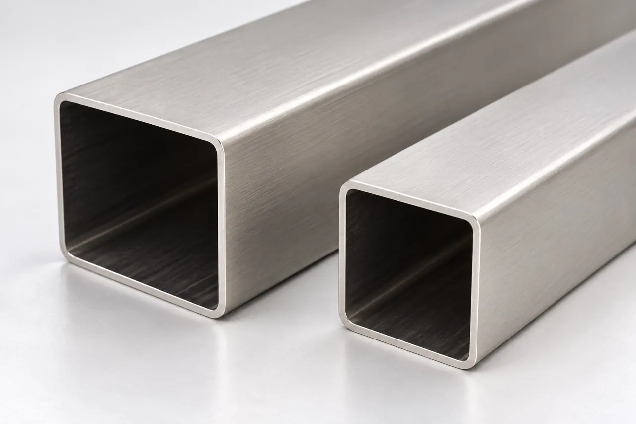
Stainless grades can look alike while responding differently to wetness, chloride exposure and cleaning. The project specification should select the alloy and account for crevices and maintenance access. A polished sample cannot verify chemistry.
Use a lot-linked material identity and an agreed finish sample as separate references. The 202 catalogue candidate is not automatically a substitute for a drawing that specifies 304 or 316.
- Exposure requirementUse the project environment and maintenance access to guide the specified alloy.
- Material referenceConnect the selected stainless designation to the represented lot and supplied tube.
- Finish referenceKeep the appearance sample separate from evidence identifying the stainless material.
Product references for your shortlist
Open the product details, then discuss the exact specification for your application.
Decorative stainless tube enquiry
A starting reference for a specified stainless section and finish to be assessed in a railing or display assembly.
Section geometry controls assembly and fixing interfaces
Specify wall, corners, seam and end condition against the fitting and project drawing requirements.
State outside dimensions, wall, corner radii, straightness, length and end condition against the drawing. Corner shape can affect fitting engagement even where nominal width matches. For a welded tube, identify seam position if it influences a visible face, bend or joint.
A safety function requires the designer's member, connection and fixing acceptance; tube appearance or a generic material-record label does not establish system load capacity.
- SectionOutside dimensions, wall and corner
- JointEnd condition and seam position
- MaterialOne selected alloy and route
- ProjectMember and fixing approval separately
Forming and welding change the decorative reference
Approve representative bends and joints because fabrication can change section geometry and visible finish.
Bending can distort a hollow section and change its surface; welding can add local heat tint, distortion and a different finish texture after blending. Make a representative joint or bend before approving a large visible batch.
Assess dimensions and appearance separately, then record the surface treatment and cleaning required after fabrication. Do not assume an approved straight length predicts the finish around every welded joint.
- ReferenceIdentified straight tube and finish
- FabricateRepresentative bend or welded joint
- InspectGeometry and blended appearance
- ApproveRecord process and project scope
A brushed direction must survive the complete fabrication
Set grain direction and local blending acceptance across the complete assembly under consistent viewing conditions.
Judge brushing on a fabricated sample
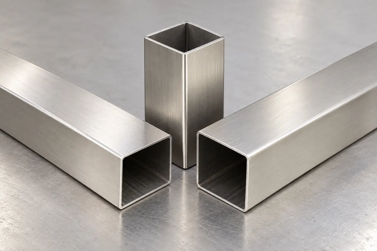
Agree grain direction, exposed faces and acceptable local blending. A surface that matches on a straight length may reflect differently when turned through a corner or joined to another member. Compare under the intended viewing direction rather than by one uncontrolled photograph.
Keep tools and handling contact appropriate to the stainless surface so transferred contamination is not confused with a changed alloy.
- Grain directionMark the direction and exposed faces before approving the decorative surface.
- Joint blendingAgree the local appearance where members meet and finishing changes the texture.
- Viewing directionCompare the complete corner or joint under the intended viewing conditions.
Acceptance records should identify the supplied product
Link supplied tube identity and dimensional evidence to the bundle and retained fabricated sample.
Use the incoming/process/final QC stages to agree which evidence addresses material identity, section dimensions and surface condition. Connect the represented batch to the marked bundle and retained fabricated sample.
No particular chemical-analysis instrument, dimensional frequency or structural approval is promised here. Ask for the required record scope and let the offer state what is included.
- Material identityLink the selected alloy and manufacturing route to the represented batch and bundle.
- Section dimensionsAgree which measurements cover the actual section, wall and relevant shape characteristics.
- Surface referenceConnect supplied finish observations with the retained fabricated sample and its accepted appearance.
Receiving protection should preserve inspection access
Keep package and tube references available while documenting transit marks or a finish mismatch.
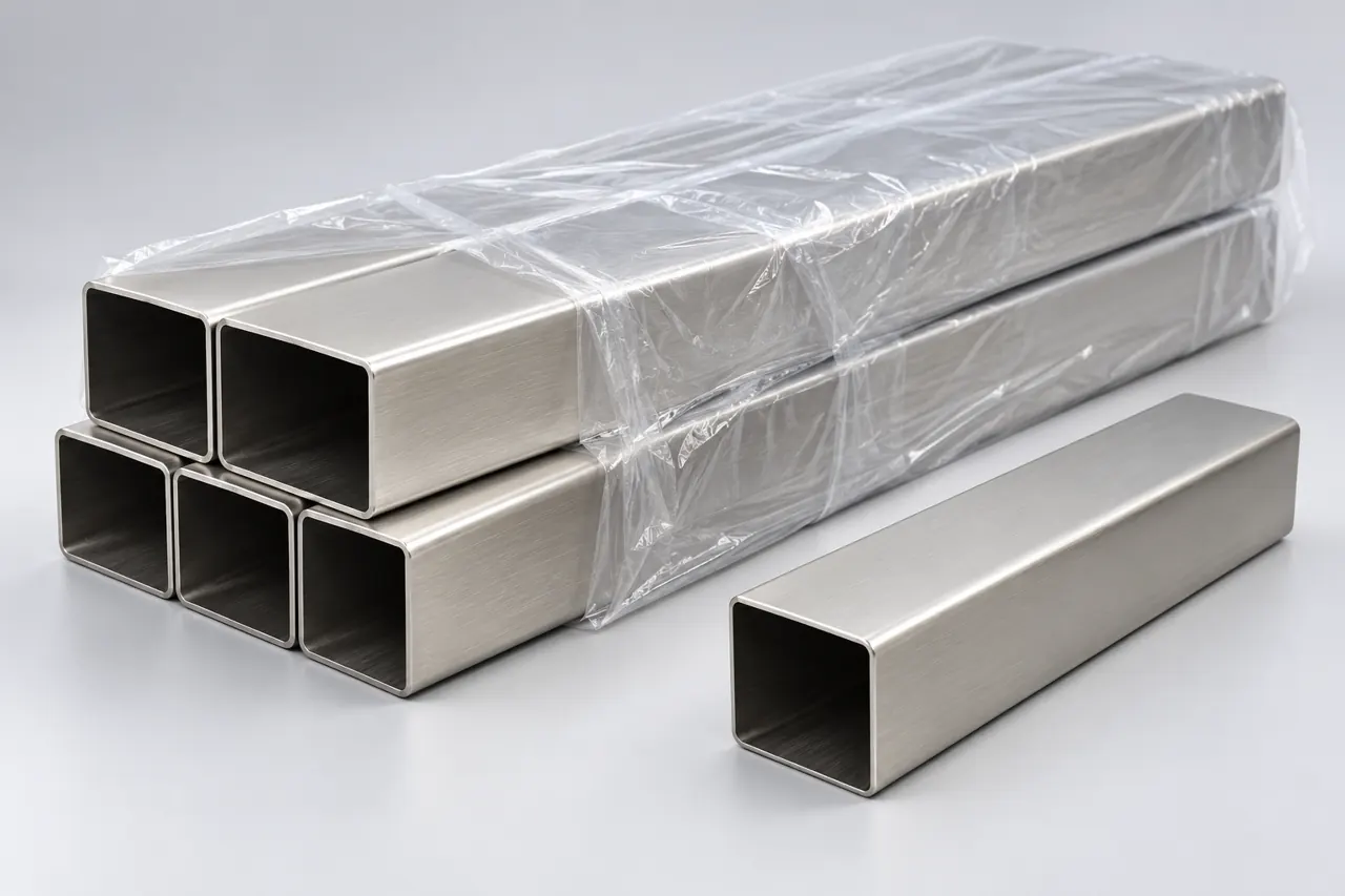
Preserve receiving context for visible surfaces
Keep packaging, surface protection and tube identity together at receipt. Record impact marks, rubbing and wetness before cutting removes the location reference. Separate transit damage from a finish mismatch observed under the agreed viewing method.
A protected bundle illustration is a handling concept, not proof of a particular film, pallet service or guaranteed mark-free transit.
- Bundle conditionRecord protection, wetness and impact marks before the bundle is dismantled.
- Tube locationKeep the affected length and face tied to the original delivery reference.
- Reference comparisonAssess finish separately from transit damage using the agreed viewing method.
Repeat orders retain section and joint appearance together
Repeat the accepted alloy, section and fabricated-joint appearance rather than matching only a straight polished length.
Freeze the selected alloy, route, section drawing and finish sample along with the accepted fabricated joint. Review proposed changes in wall, seam location or finishing before release.
For display frames, this protects fitting and appearance consistency. For railings, it supports material supply control while structural and site-fixing acceptance remain with the project requirements.
- ApproveAlloy, section and finish
- SpecifyProcessing and protection scope
- ReceiveMatch labels and reference samples
- ReorderRetain accepted requirements
Define the frame and visible finish
Send the tube drawing, service role and exposure so material and finishing responsibilities can be defined.
Send the section drawing and a representative joint or finish reference so we can discuss the actual tube, protection and processing scope for your assembly.
Qingdao Relia Industries Co., Ltd.
Contact address: Shuyuan Road, Qingdao, Shandong, China
- Selected alloy and service exposure
- Outside dimensions wall and corners
- Lengths joints and seam position
- Visible faces and finish reference
- Assembly role and design requirements
Enquiry scope and supporting detail
Send the specified alloy, section dimensions, wall, lengths, visible-face and joining details. Identify whether the item is a display, frame or safety-related railing, and include exposure, cleaning and finish acceptance. We can then define the offered tube and manufacturing/finishing responsibilities without turning decorative appearance into a structural or corrosion guarantee.
- MaterialAlloy · section · wall · length
- AppearanceFinish sample · visible faces
- SupplyProcessing · protection · quantity