
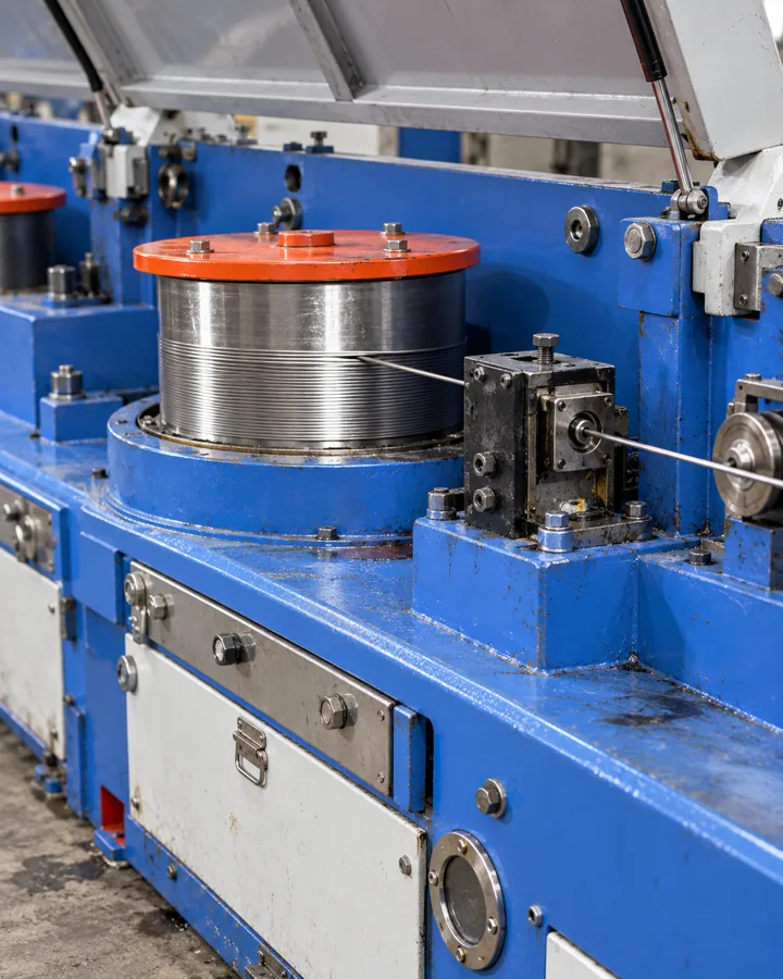
Deburring and Edge-Rounding Machines for Laser-Cut Sheet
Choose a deburring machine from real laser-cut parts and the edge result you need. This guide helps you separate burr removal from rounding, test small parts and internal features, and protect sensitive faces. A representative sample matrix then connects the selected configuration with output quality, handling and the site requirements of your production mix.
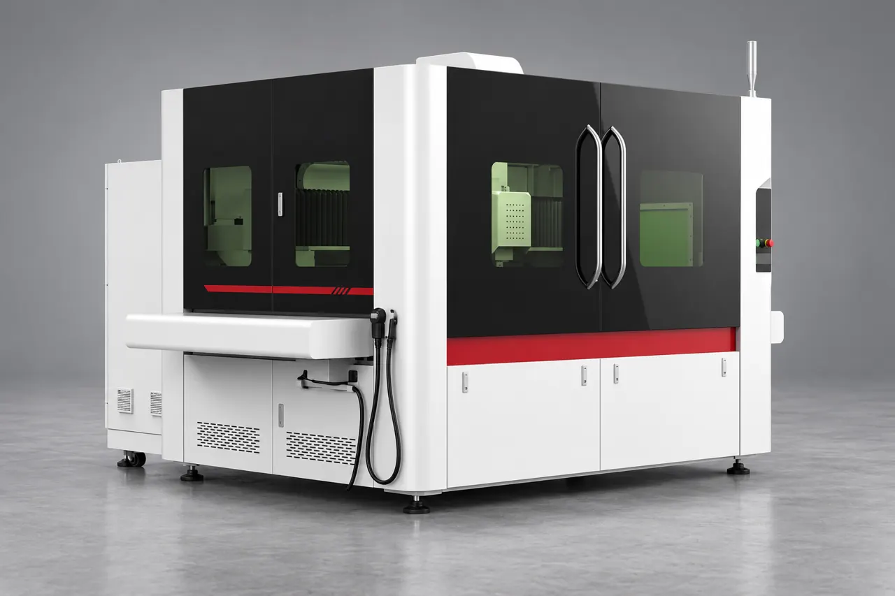
Choose the machine around real cut parts
If laser-cut parts still need hand work, choose a deburring machine from representative burrs and the required edge result rather than maximum working width alone. Start with part material, thickness, smallest features and acceptable face finish, then separate burr removal from edge rounding. Relia supplies equipment and selection support; it is not the machine manufacturer. Send a mixed sample set from your normal cutting process so the selected RES configuration can be assessed for hold-down, internal features and repeatable acceptance before a purchase specification is agreed.
- Starting burrShow actual burr location and attachment on representative parts from your normal cutting process.
- Required edgeDefine removal, rounding and face-finish acceptance as distinct output requirements.
- Production mixInclude limiting features and handling conditions when selecting the proposed equipment configuration.
Selection context and decision detail
| Buyer requirement | Relia response | Evidence / condition |
|---|---|---|
| Specified edge result | Equipment supply and selection support | Actual burr, material and final edge criteria |
| Usable part range | Model/configuration review | Hold-down, features, finish and site interface |
| Reviewable acceptance | Maker evidence and sample trial | Recorded setup and distinct factory/site scope |
Equipment selection is a supply and evidence responsibility
Define the actual maker, model and checks through the equipment supply offer, with commissioning responsibility clearly assigned.
Relia supports equipment supply and selection; machinery manufacture is not claimed. Company incoming, in-process and final QC with corresponding batch records is confirmed. For a machine order, assign the actual maker's configuration checks, outgoing evidence and commissioning responsibilities rather than treat those company facts as a manufactured-machine test result.
Product 957 offers RES800/RES1000/RES1300. Its overall 0–1300 mm range, PLC, 380 V and 45 kW fields do not establish each model's usable width or installed electrical requirements. Video and test-report availability is not an actual trial result.
- Supply responsibilityRelia supports equipment selection and supply while the actual machine maker remains identified.
- Selected configurationConfirm usable width, installed electrical needs and included units for the selected RES model.
- Assigned checksSeparate maker configuration checks, outgoing evidence and site commissioning responsibilities in the offer.
Incoming burr and final edge are separate definitions
Describe incoming burrs and required edge geometry separately because removing a projection does not establish an accepted radius.
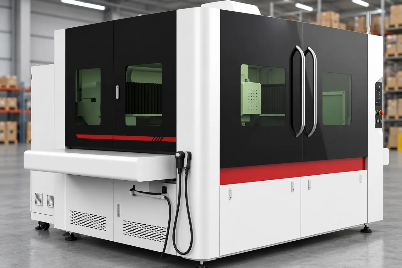
Burr removal and edge rounding are different results
A burr projects from the cut edge; rounding removes or reshapes the edge itself. Removing a vertical burr does not automatically create the required radius around an internal slot or hole.
Describe burr location, size and attachment alongside the required edge break/radius and the faces that must retain their finish. Use actual cut samples rather than a verbal burr-free requirement alone.
- Incoming projectionDescribe the burr’s location, size and attachment before the sample enters the machine.
- Required edge shapeSpecify the accepted edge break or radius at external and internal features.
- Protected faceIdentify surfaces that must retain their finish while the edge is treated.
Product references for your shortlist
Open the product details, then discuss the exact specification for your application.
RES deburring and edge-rounding enquiry
An equipment supply reference for selecting a RES configuration through representative laser-cut parts and defined edge acceptance.
Abrasive contact links tool choice to the result
Match actual abrasive units and contact conditions to the burr while controlling support and unwanted face changes.
Abrasive selection and contact remove material from burrs and adjacent surfaces. Contact pressure, exposure and part support influence the balance between burr removal, rounding and unwanted face change. The required tool arrangement must suit the actual burr and material.
Do not transfer another maker's belt or brush configuration to the RES machine; confirm the offered units and trial setup.
- Actual abrasive unitsConfirm the offered tooling arrangement against the burr and material in the sample set.
- Contact and exposureRecord pressure and exposure conditions that balance burr removal with the intended rounding.
- Part supportCheck support and protected faces because unwanted movement or face change can affect acceptance.
Small parts and internal features test usable capacity
Trial the smallest parts and internal features because nominal machine width cannot establish hold-down or edge access.
Define the smallest part footprint, holes, slots, thickness range and orientation the line must handle. A wide machine is not automatically able to retain a small cutout or reach every internal edge.
Trial the limiting feature and check both retained part dimensions and the intended edge. Agree required support/hold-down and any parts that need a separate route.
- Smallest footprintTrial the smallest required parts with the proposed support and hold-down arrangement.
- Internal featuresCheck holes and slots for both intended edge treatment and retained component dimensions.
- Separate routeIdentify parts the selected configuration cannot support or reach through the agreed process.
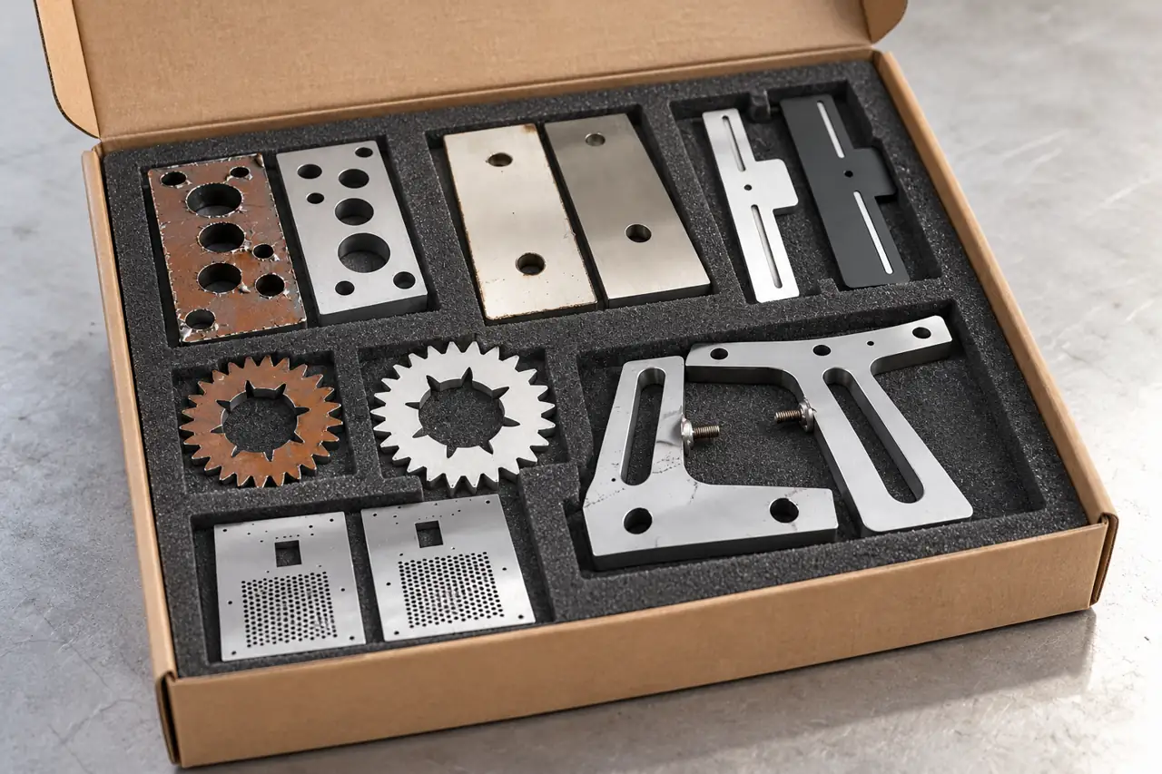
A sample matrix prevents an easy coupon from setting the specification
Include difficult burrs, thin pieces and sensitive faces, recording the actual tools, passes and sample results.
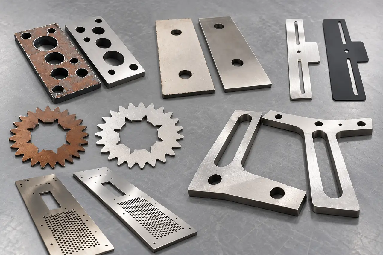
Build a sample matrix that exposes limits
Include typical parts plus difficult burrs, thin pieces, internal profiles and sensitive faces. Record incoming condition and accepted output, with the actual tool, feed/pass arrangement and orientation.
Measure edge result and relevant dimensions using the agreed method. Before/after pictures help locate change but cannot alone verify a numerical radius.
- Typical productionInclude parts representing normal materials, thicknesses and the usual incoming burr condition.
- Difficult geometryAdd thin pieces, internal profiles and the smallest features the process must handle.
- Recorded outputRetain setup and accepted samples with measured edge, surface and dimensional results.
Material changeovers need a defined handling plan
Plan material changeovers with the selected tooling and site documentation so contamination and handling needs remain explicit.
Carbon steel, stainless and aluminium may require different tooling and contamination controls. Define which materials share the process and how parts, abrasives and extraction are managed between them.
Review the actual machine documentation and site provisions for the selected use. A multi-metal application list does not establish every dust-handling or surface-cleanliness requirement.
- Material mixState which carbon-steel, stainless and aluminium parts are intended to share the process.
- Tooling and handlingDefine how parts and abrasives are managed to meet the required contamination boundary.
- Site provisionsReview extraction and operating requirements in the selected machine and site documentation.
Acceptance should connect output quality and operating conditions
Keep machine function, workpiece performance and site acceptance separate, linked by the actual operating and consumable conditions.
Connect acceptance with the actual trial conditions
Agree which parts, edge criteria, face finish, throughput observation and consumable condition define the trial. Separate machine functional checks from workpiece performance and from the buyer's site acceptance.
The cabinet illustrations do not expose a verifiable abrasive layout or identify an actual offered RES model; confirm configuration through drawings, records and the trial.
- Selected configurationRecord the machine identity and actual tooling arrangement used for the part trial.
- Workpiece resultAgree parts, edge criteria and face finish together with the observed operating conditions.
- Site acceptanceAssign functional checks and commissioning separately from the demonstrated workpiece processing result.
Retained parts make future setup changes reviewable
Retain incoming and output samples with the accepted setup so tool wear or part changes can be reviewed meaningfully.
Keep identified incoming/output samples and the accepted setup with the configuration record. Tool wear, replacement or changed part geometry can change the result even while the machine still runs normally.
Do not promise one radius, feed rate or finish for every listed metal. Repeatability needs the actual agreed operating window and verification basis.
- Matched samplesKeep identified incoming parts and accepted outputs with the actual configuration record.
- Accepted setupRetain operating and consumable conditions defining the successful edge and surface result.
- Change observationsReview tool wear, replacement and changed part geometry against those retained references.
Build the burr and edge sample package
Send representative parts and edge criteria to define a selected configuration, trial and clearly assigned equipment-support scope.
Send typical parts and the difficult features from your cutting process so we can discuss a configuration and trial focused on the edge result you need.
Qingdao Relia Industries Co., Ltd.
Contact address: Shuyuan Road, Qingdao, Shandong, China
- Material thickness and part drawings
- Burr locations and retained samples
- Smallest parts holes and slots
- Required edge and protected faces
- Production mix and site utilities
Enquiry scope and supporting detail
Send drawings and physical samples identifying material, thickness, burr location, smallest part/features and protected faces. State the required edge acceptance, relevant dimensions, production mix and site utilities. We can then define a model/configuration enquiry and witnessed trial scope, with maker, commissioning, documentation and commercial responsibilities recorded.
- PartsMaterial, thickness, drawings and geometry
- AcceptanceEdge, surface and dimensional checks
- EquipmentConfiguration, installation and support needs