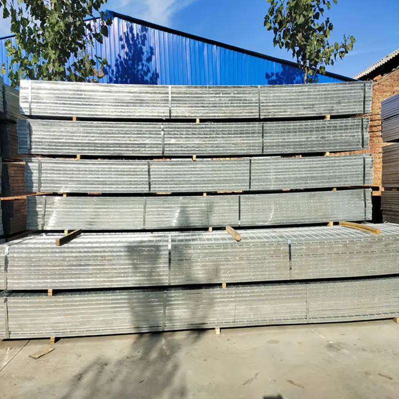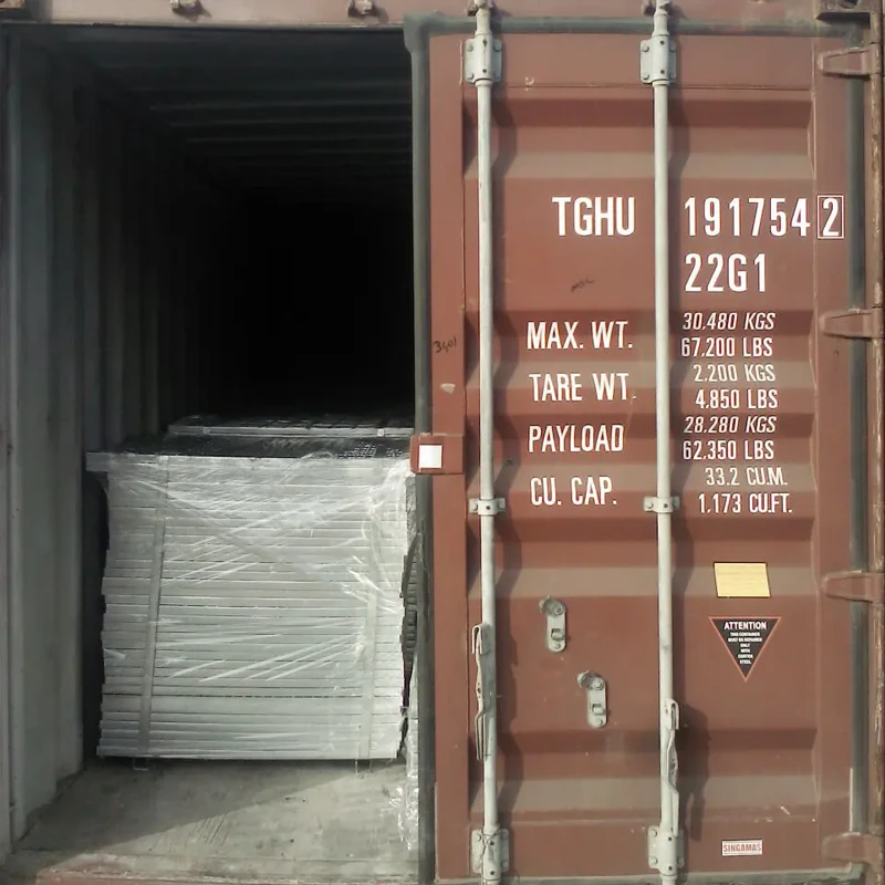
Galvanized Steel Grating Supplied to Project Drawings
For platform, access-way and stair-project buyers, select galvanized steel grating from the engineer's load and support arrangement before choosing a panel size. Bearing-bar depth, thickness, spacing and span determine the load-carrying geometry; a zinc finish does not establish a rating. The listed grating candidate supports a drawing-based enquiry for custom panels. Send the panel schedule, bearing direction, openings and fixing requirements so the offered construction can be compared with the project specification. Release should connect panel geometry and finish records to the approved design and installation marks.
| Buyer requirement | Relia response | Evidence or condition |
|---|---|---|
| Approved platform geometry | Review drawing-based galvanized grating supply | Engineer defines load, support and fastening conditions |
| Correct bearing construction | Specify bar depth, thickness, pitch and direction | Offered section and fabrication details match design |
| Traceable panel acceptance | Reconcile panel marks, dimensions and finish records | Actual order defines fabricator and coating scope |
Panel supply needs a defined fabrication scope
Relia can review the listed galvanized grating against project drawings and the panel schedule. Relia manufactures steel plate and coil, including hot or cold rolling for the selected product. That confirmed scope does not establish in-house grating fabrication or batch galvanizing of finished panels. The offer should identify those responsibilities and any supplied fixings.
Incoming, in-process and final inspection are performed in Relia's confirmed manufacturing operations, with corresponding batch records available. For the grating supply, agree the fabricator's dimensional and coating evidence, receiving checks and panel-to-record traceability applicable to the actual order.
- 01FabricationNamed panel producer and drawing revision
- 02FinishingGalvanizing scope and acceptance
- 03Quality evidenceApplicable dimensional and batch records
- 04Project interfaceFixings, supports and approval authority
Bearing-bar geometry carries the design decision
Describe bearing bars by depth and thickness, then define their centre spacing and span direction separately from cross-bar pitch. For an unnotched rectangular bar, bending stiffness depends strongly on its depth; equal panel width or equal mass does not establish equal deflection under load.
The listing contains thickness and spacing references, but the complete offered section belongs in the technical quotation. Give the clear support span, support bearing, load type and engineer's acceptance limits. The design review must use the proposed construction, rather than borrowing a load table for a superficially similar grid.
- 01SectionBearing-bar depth and thickness
- 02LayoutBearing spacing and cross-bar pitch
- 03DesignClear span · support · actual load
- 04ComparisonProposed construction against approved criteria
Samples confirm construction rather than a platform rating
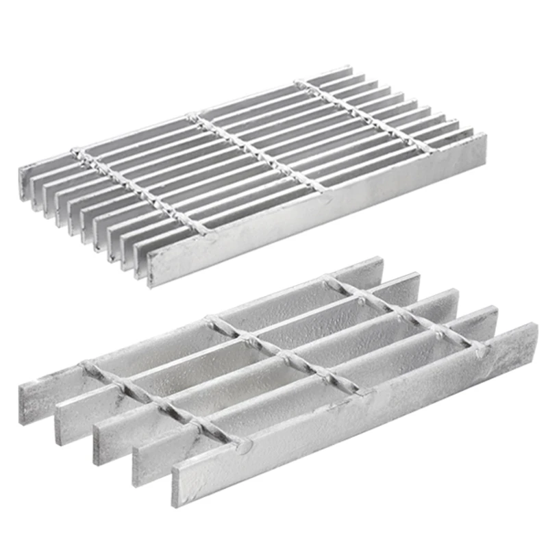
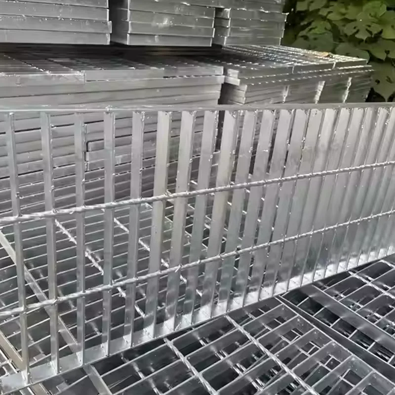
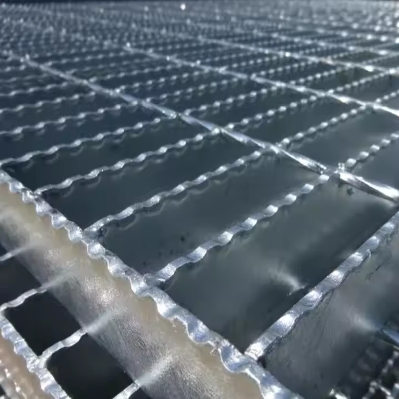
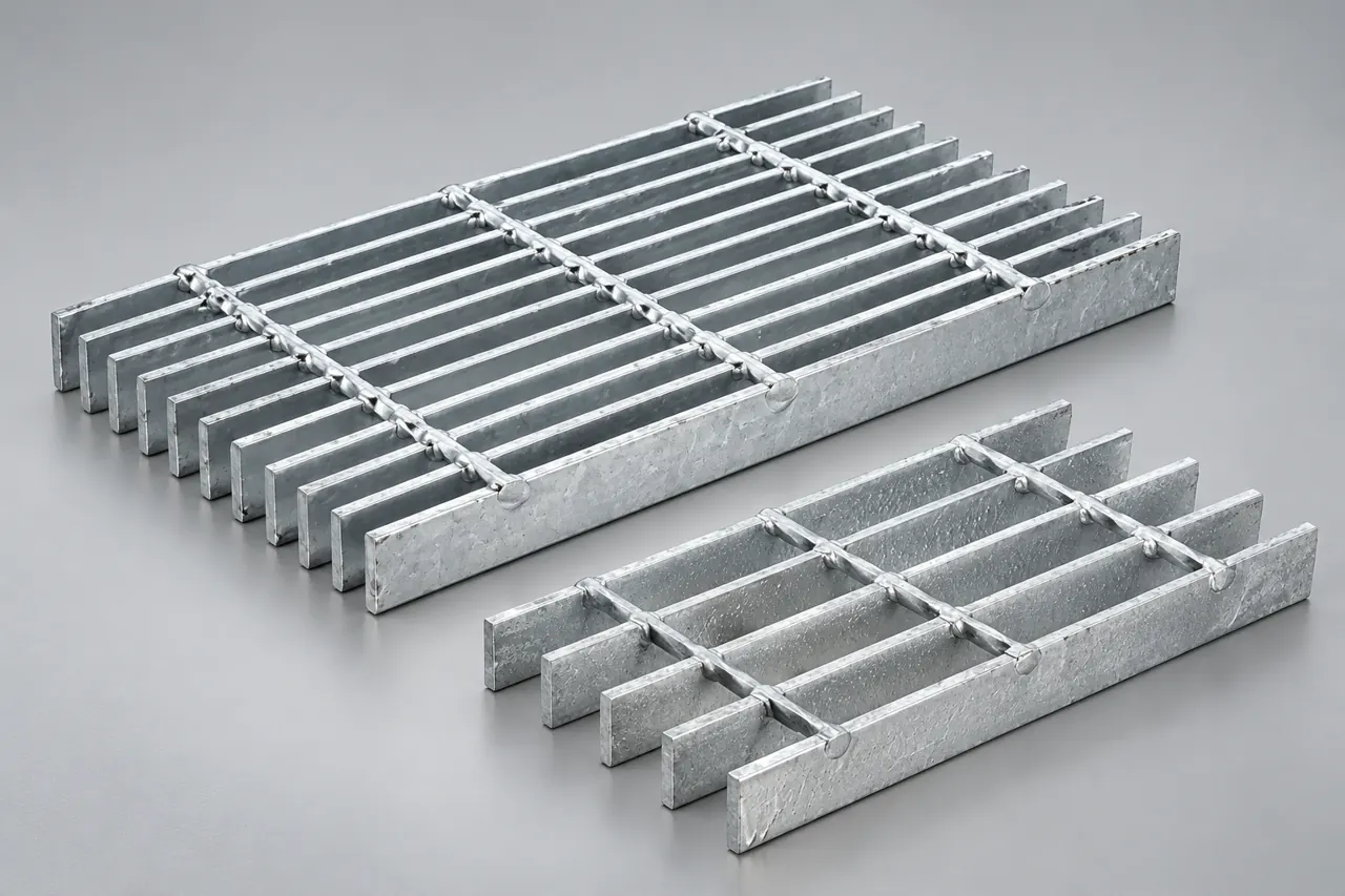
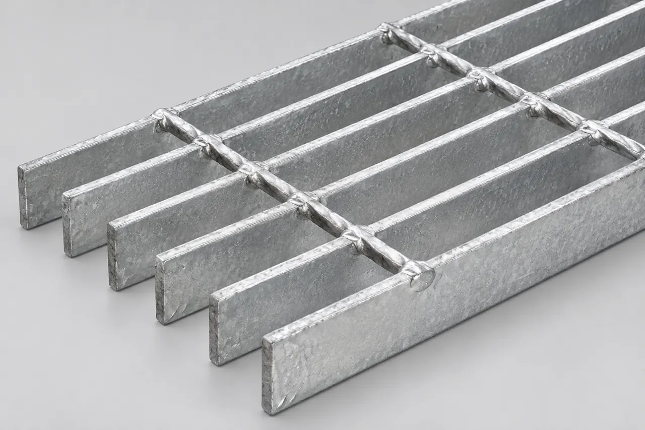
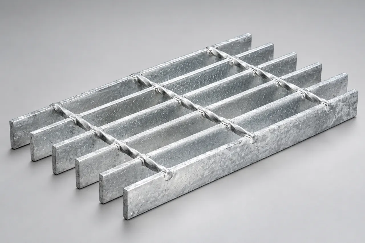
The images show flat bearing bars joined to smaller cross bars, which is relevant to bar-grating construction. They do not reveal the full panel boundary, installed support or a tested load capacity. Use a representative sample to confirm bar orientation, pitch, joint form and surface detail.
Compare the sample with the approved drawing and offered construction. A change in joining method or bar arrangement needs review because load distribution and rigidity can differ. Keep photographs with the panel reference; the AI-assisted illustrations here are not the identified approval sample.
Openings and edges preserve the intended load path
An opening through bearing bars interrupts the elements carrying load to the supports. Notches, penetrations and edge banding therefore need locations and details on the engineer-approved drawing. Site cutting should not be treated as a harmless adjustment to a panel selected for a different geometry.
Define edge treatment, clearance around services and any reinforcement or additional support. Distinguish load-carrying details from trim used only to finish an edge. Confirm the fixing type and supplied scope, including how movement or uplift is addressed by the project design.
- 01InterruptionCutout or notch position
- 02Load pathEngineer-defined support or reinforcement
- 03EdgesLoad-carrying banding or trim detail
- 04FixingSupplied hardware and design interface
Galvanizing controls exposure and fit
Hot-dip galvanizing protects the steel surface; coating thickness, continuity, adherence and finish are separate from structural section acceptance. If ASTM A123/A123M is specified, the relevant fabrication category and steel thickness govern the coating requirement. The catalogue zinc reference is not a universal project acceptance value.
Review welded intersections, drainage and edges for the agreed finish criteria. Local excess zinc can interfere with mating surfaces or clips. State any appearance requirements beyond functional acceptance before supply. A bright or dull sample surface alone does not establish coating conformity or service life.
Acceptance should reconcile design, fabrication and finish
Use the panel mark to connect the approved drawing, material identity, dimensional results and coating records. Measure overall dimensions and critical openings with the bearing direction clearly identified. Inspect the supplied joints and edge details against the accepted fabrication scope.
Project performance remains tied to the engineer's load, span, support and fastening assumptions. Where a proof test or special slip criterion is required, specify the method and responsibility in advance. Do not infer either from a generic platform application or a list of unrelated standard acronyms.
- 01DesignLoad · span · support · fastening
- 02FabricationPanel size · bars · joints · openings
- 03FinishCoating requirement and inspection
- 04IdentityPanel mark linked to drawing and results
Installation groups should remain distinguishable
A panel can have the correct dimensions yet be unsuitable in the wrong orientation or location. Organise the delivery schedule by panel mark, revision and installation area, with quantities reconciled to bundles. Specify which faces and edges need protection during transport and handling.
Receiving staff should be able to distinguish mirrored openings and similar panels without improvising a fit. Packing and marking requirements are agreed order details; the article does not promise a particular labelling service. Retain the approved schedule when installation is split across multiple delivery groups.
- 01ScheduleMark and revision per installation area
- 02DistinguishOrientation and mirrored openings
- 03ReconcileBundle contents and quantities
- 04ProtectAgreed faces, edges and handling interfaces
A dimensional discrepancy needs an oriented record
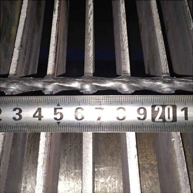
Record a discrepancy using the panel mark, bearing direction, support side and drawing reference. Photograph the affected opening, edge or joint with a scale and locate each measurement on a sketch. Preserve the coating condition before repair or installation changes obscure it.
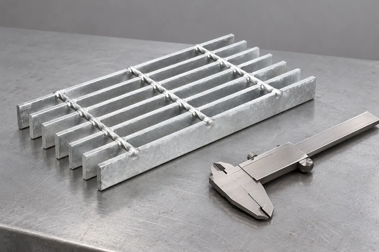
The illustrated grating and caliper provide inspection context only; they are not a measured result. If a panel differs from its drawing, review the fabrication evidence and engineering consequence before acceptance. Coating repair and structural modification require their own agreed dispositions.
Send the panel schedule with design and finish requirements
Provide the drawing revision, panel marks and quantities, bearing-bar section and direction, clear spans, supports and engineer-defined loads. Add cutouts, banding, fixing scope and the specified galvanizing acceptance. Identify any required dimensional reports, material documents or project-specific tests.
Relia can compare this package with the selected grating proposal and clarify fabrication, finishing and record responsibilities. Resolve design departures in the technical offer before purchasing, then retain one accepted schedule for fabrication review, receiving and installation.
- 01DesignLoads · clear spans · supports
- 02PanelMarks · section · pitch · direction
- 03DetailsCutouts · banding · fixing scope
- 04AcceptanceGalvanizing · geometry · project records
Contact address: Shuyuan Road, Qingdao, Shandong, China
Technical references and scope
- NAAMM — Metal Bar Grating Engineering Design Manual MBG 534-24
- NAAMM — Metal Bar Grating Manual MBG 531-24
- American Galvanizers Association — ASTM Specifications
General process and test references explain selection principles. The selected product specification and order records govern acceptance.