Flat Binding Wire for Automatic Feeding and Tying
For an automatic feeder, flat binding wire needs a defined cross-section and coil format as well as a material description. We list galvanized flat binding wire for industrial enquiries. Share the feeder interface and tying requirement so the offered width, thickness and supplied coil can be checked together in a practical trial.
Width and thickness define two different constraints
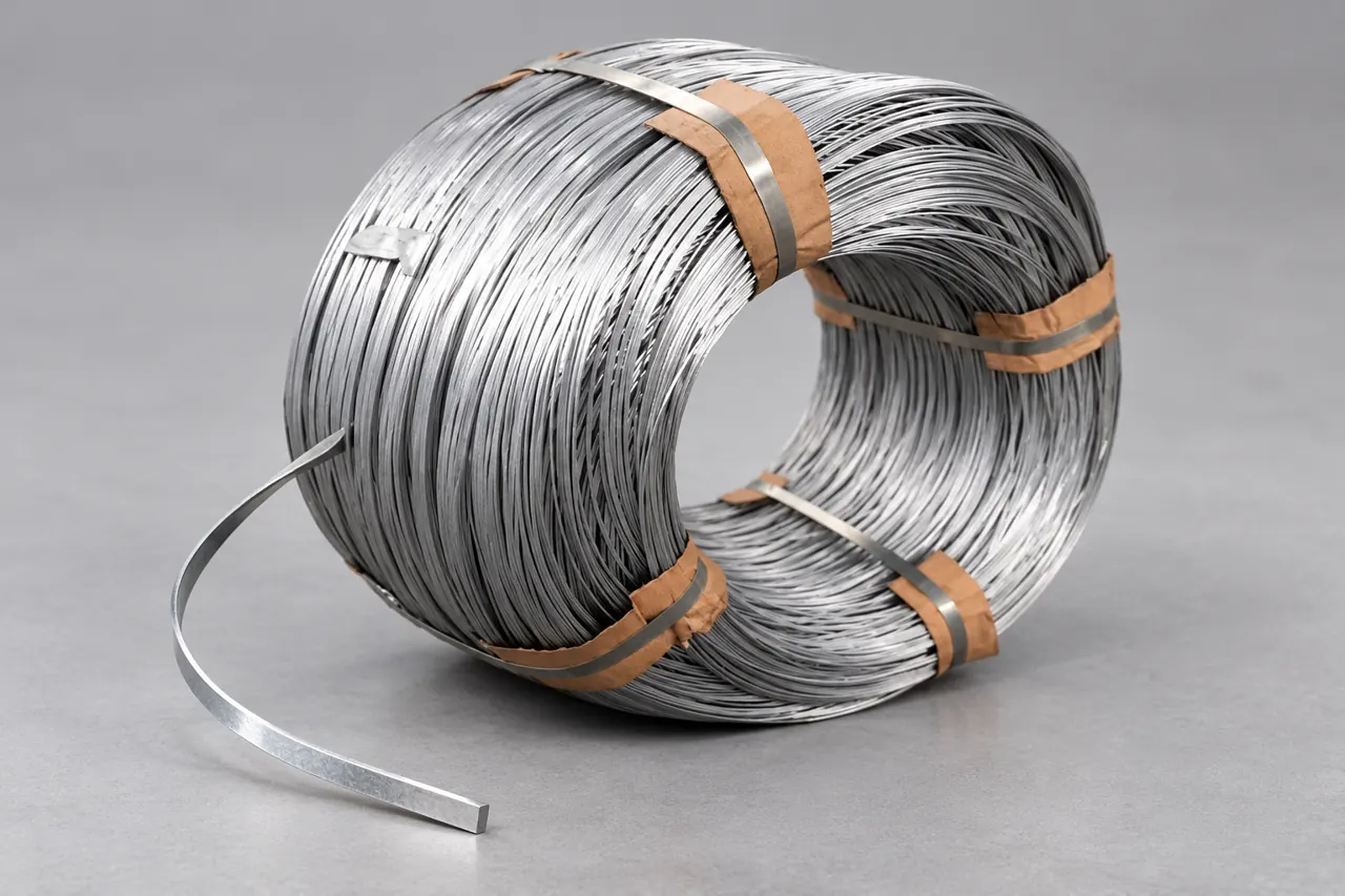
Specify width and thickness separately, with tolerances and the measurement method. Add the edge condition and the intended material or coating. A gauge label or a single diameter figure cannot describe a rectangular cross-section, and a general strip description may leave the required binding-wire behaviour unresolved.
The feeder interface belongs in the enquiry
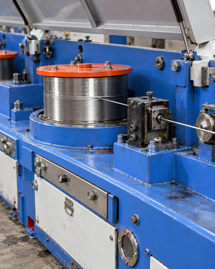
Describe the guiding arrangement, coil support and tying motion without assuming that all automatic lines accept the same wire. Include permitted coil dimensions and the direction in which material pays off. If a machine drawing is confidential, provide the interface limits needed to review supply rather than the entire machine design.
Edge and surface samples make subjective words testable
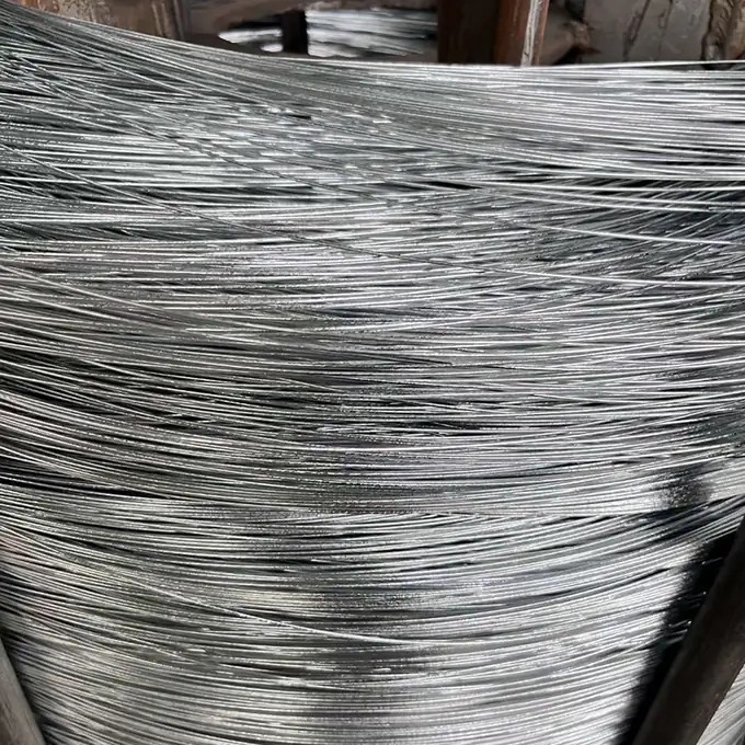
Ask for a sample that shows the proposed edge and coating condition. Agree how burrs, surface marks or coating damage will be judged where they affect feeding or the finished tie. A smooth-looking photograph is helpful context, while the sample and written acceptance basis define the actual requirement.
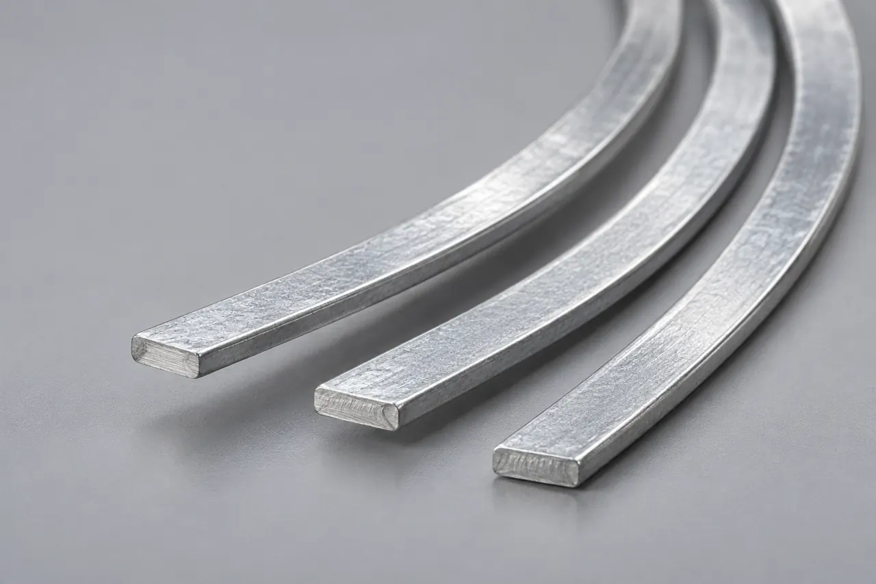
A short run should record where feeding fails
Trial the candidate with your intended coil handling and representative production settings. Record stoppages, guide interference, twisting and finished-tie condition. Note the wire and coil identity alongside equipment adjustments, so a result is not attributed to the material when the setup changed at the same time.
Coil format can change the practical outcome
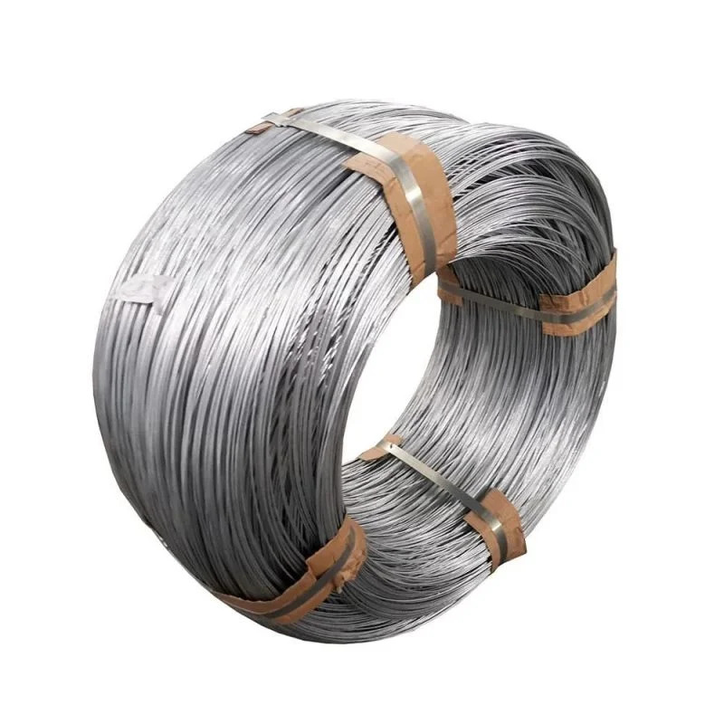
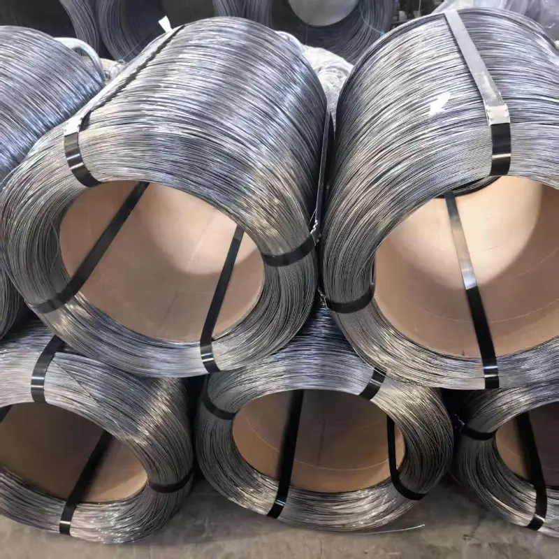
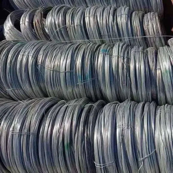
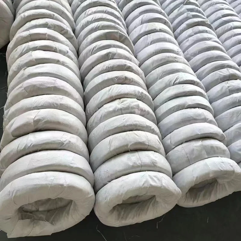
Two coils of similar wire may behave differently in the same handling arrangement. Define the inner and outer dimensions, maximum handling mass and packaging needed to preserve the coil. Confirm these limits in the offer, and assess the actual proposed format rather than relying on an illustration of a loosely wound bundle.
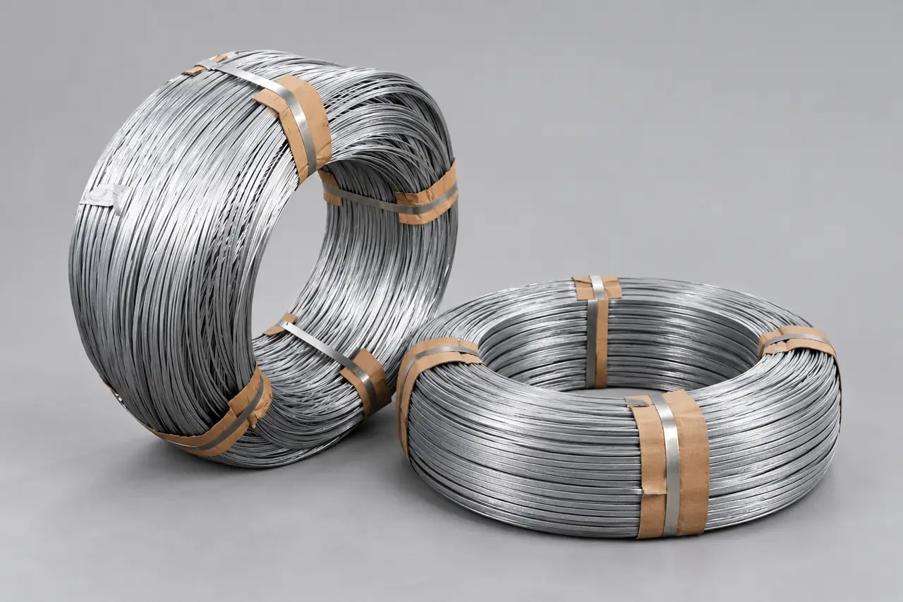
Evidence should address the feature that matters
For a section issue, request measurements with the sampling basis. For a feed issue, retain the relevant coil and run observations. For a coating issue, identify the agreed inspection requirement. We can discuss the catalogue item and the available records for the proposed supply without inventing a machine-compatibility guarantee.
Packing should preserve coil identity and orientation
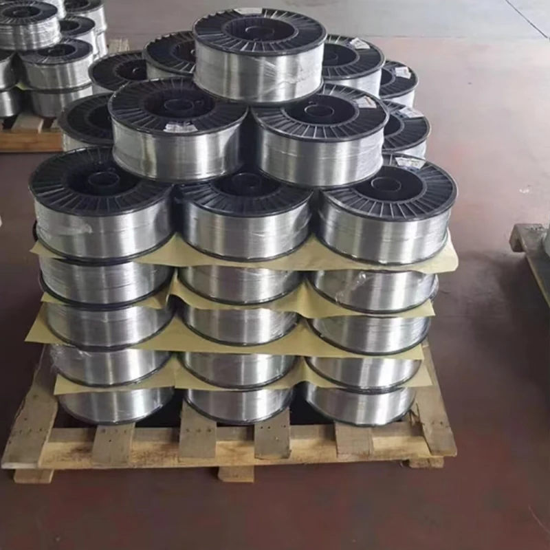
Show which labels your receiving team needs and how coils should remain separated. State any required payoff orientation on the packing brief. Confirm protective wrapping and handling arrangements before shipment, along with the purchase unit and quantity basis; a total mass alone may conceal an unsuitable number or size of coils.
An approved sample should remain a physical reference
Keep a short section sample and the coil-format record after trial approval. If a later delivery feeds differently, compare the actual material and packing with that reference and retain the affected lot. This gives the discussion a repeatable basis beyond descriptions such as too stiff or not feeding well.
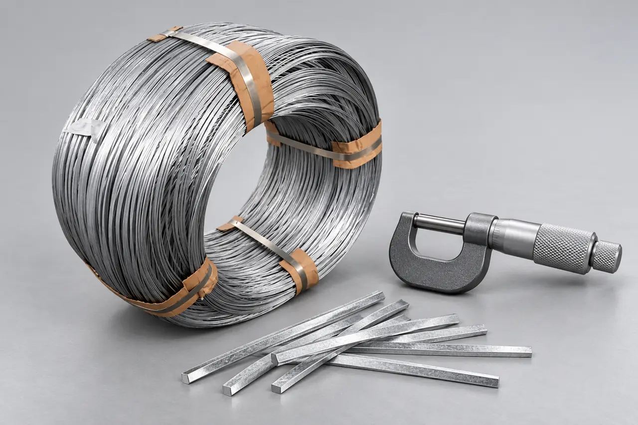
Send the section and feeder limits together
Provide width, thickness, edge requirements and material identity, followed by coil dimensions, payoff arrangement and trial quantity. Add the acceptance method, packing and destination. Our team can review the listed flat-wire option and confirm a specific offered section and coil format before you arrange a production trial.